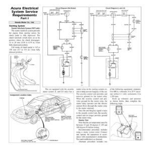
Acura Electrical System Service Requirements Part I Honda Motor Co., Ltd. Starting System Starter Interlock System (M/T only) The starter interlock system prevents the engine from starting unless the clutch pedal is fully depressed. The clutch interlock switch turns on at the position where the clutch disengages: 15 to 20 mm (0.59 to 0.79 in.) from fully depressed position. Full stroke of clutch pedal is 145 to 150 mm (5.7 to 5.9 in.) from fully released position. CLUTCH f INTERLOCK { Circuit Diagram (Std Model) UNDER-HOOD RELAY BOX IGNITION SWITCH No. 22 No. 26 BATTERY (70 A} (40 A) o_p 3S D WHT STARTER UNDER-HOOD RELAY BOX No.22 BATTERY (70A) No.26 (40a) CLUTCH INTERLOCK SWITCH (MIT onty) G14 Circuit Diagram (L and LS) DASH FUSE BOX IGNITION SWITCH BLK/YEL CLUTCH INTERLOCK SWITCH (MIT only) BLK/YEL (A/T) BLU (M/T) STARTER BLK/YEL SECURITY CONTROL UNIT The car equipped with the security alarm system (L and LS only) has a Component Location Index STARTER DASH RELAY HOLDER {Located under dash, left side) SECURITY CONTROL SHIFT POSITION UNIT (L and LS only) CONSOLE SWITCH (Located under driver’s (NEUTRAL SAFETY SWITCH) _ seat) {A/T only) STARTER RELAY starter relay in the starting system cir- cuit to help prevent burglary of the car. The security control unit provides and removes ground for the starter relay. When the security control unit pro- vides ground for the starter relay, the starter relay operates and the electric current flows through the starter relay to the starter solenoid. Once the anti-burglary signal is input to the security control unit, the security control unit no longer provides ground for the starter relay. Starter Test Note that the air temperature must be between 15 and 38 degrees C (59 and 100 degrees F) before testing. Recommended procedure includes using a starter system tester. Connect and operate the equipment in accor- dance with manufacturer’s instructions. Test and troubleshoot as directed. Alternate procedure includes use of the following equipment: ammeter, 0 to 400 A; voltmeter, 0 to 20 V (accu- rate within 0.1 volt); tachometer, 0 to 1,200 rpm. Hook up voltmeter and ammeter as shown below, then complete the following steps: BATTERY GROUND WIRE