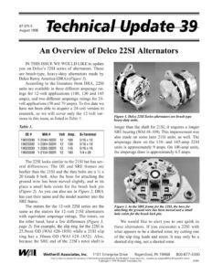
87-375-5 August 1998 An Overview of Delco 22SI Alternators IN THIS ISSUE WE WOULD LIKE to update you on Delco’s 22SI series of alternators. These are brush-type, heavy-duty alternators made by Delco Remy America (DRA) (Figure /). According to the literature from DRA, 22SI units are available in three different amperage rat- ings for 12-volt applications (100, 130 and 145 amps), and two different amperage ratings for 24- volt applications (50 and 70 amps). To this date we have not been able to acquire a 24-volt version to research, so we will cover only the 12-volt ver- sions in this issue, as listed in Table 1. Table 1. OE # WAI # Volt Amp. B+Terminal 19020300 1-2044-00DR 12 100 5/16 x 18 19020302 1-2064-00DR 12 130 5/16 x 18 19020303 1-2065-00DR 12 145 5/16 x 18 19020308 1-2154-00DR 12 100 1/4 x 28 The 22S] looks similar to the 21SI but has sev- eral differences. The DE and SRE frames are beefier than the 21SI and the thru bolts are a 4 x 20 Grade 8 bolt. Also the boss for attaching the ground wire has been moved slightly, and in its place a small hole exists for the brush lock pin (Figure 2). As you can also see in Figure 2, DRA has cast their name and the model number into the SRE frame. The stators for the 12-volt 22SI series are the same as the stators for 12-volt 21SI alternators with equivalent amperage ratings. The rotors, on the other hand, have a few differences (Figure 3, page 2). For example, the slip ring for the 22ST is 25.9mm OD (WAI #28-1858) while a 21SI slip ring has a 30mm OD (WAI #28-1852). Also, because the SRE end of the 22SI’s rotor shaft is Figure 1. Delco 22SI Series alternators are brush-type heavy-duty units. longer than the shaft for 21SI, it requires a longer SRE bearing (WAI #8-109). This improvement was also made on some later 21SI units, as well. The amperage draw on the 130- and 145-amp 22SI units is approximately 9 amps. On 100-amp units, the amperage draw is approximately 6.5 amps. Figure 2. In the SRE frame for the 22ST, the boss for attaching the ground wire has been moved and a small hole exists for the brush lock pin. We would like to alert you to one quirk in these alternators. If you encounter a 22SI with what appears to be a shorted rotor, try cutting one of the slip ring leads and retest. It may only be a shorted slip ring, not a shorted rotor. / fai | Wetherill Associates, Inc. 1101 Enterprise Drive — Royersford, PA 19468 800-877-3340 Care is taken to ensure the accuracy of information presented here, but Wetherill Associates, Inc., assumes no responsibility for possible errors. Copyright © 1998 Wetherill Associates, Inc. JOBN Technical Update 39 page 2 Figure 3. Stators for the 12-volt 22S1I are basically the same as those for the 21SI. Rotors have a smaller slip ring and a longer shaft. The voltage regulator and rectifier for the 12- volt 22SI are the same as those used in 21SI units with comparable amperage ratings (Figure 4). When you look at the electrical components, notice the small sponge pad on the rectifier side of the diode trio. This is to dampen the vibration and pre- vent fracture to the diode trio’s connector straps. 40-ohm resistor Autostart Figure 4. The regulator and rectifier in the 12-volt 22ST are the same as those used in the 21SI. In Figure 4, you will also note a feature unique to the 22SI: the autostart-and-trio assembly. The autostart is a circuit attached to a standard diode trio that allows the 22SI to turn on at a much lower RPM than the 21SI, without an electrical draw on the battery. The circuit has four connections to the alternator. These connections go to ground, the sta- tor, B+ and the output leg of the diode trio (regula- tor) (Figure 5). Stator Ground Figure 5. The autostart cir- cuit on 22ST units has four connections to the alternator. Diode trio output Bt+ Although you test this diode trio the same as any other diode trio, there is a specific procedure for testing the autostart circuit. According to the Delco service manual, the procedure for testing the autostart is as follows: Use ohmmeter to check autostart and trio assembly. Place negative lead of ohmmeter on regulator strap and positive lead to the auto start and trio assembly B+ ter- minal. The meter should indicate open circuit. Reverse the ohmmeter leads and the reading should indicate continuity. If either reading is incorrect, replace the entire autostart-and-trio assembly. This procedure tests only the power transistor, not the entire autostart system. We have also found that some ohm meters are not capable of making this test. In order to do a complete test of the autostart system you need expensive sophisticated equipment. The autostart system is designed to be turned on only during startup. However, in early 22SI units, ripple voltage from a battery charger could turn on — and keep on — the autostart, which would destroy it. The first fix for this problem was to install a 40-ohm resistor on the inside of the alter- nator from a stator terminal to ground, using the stator terminal farthest from the autostart assembly (Figure 4). The later version of the autostart-and- trio assembly has this resistor built into it. In March, 1998, Navistar issued another fix for this problem in their “Authorized Field Change G- 97906.” This document announced a program to Assembled brush holder Long brush Brush-lock pin hole Figure 6. The 22SI has a new-style brush holder with very long brushes and a unique brush spring. The brushes and brush spring are tricky to install.