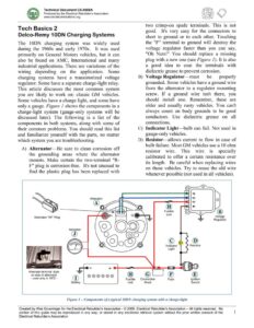
Technical Document CS-0908A Produced by the Electrical Rebuilder’s Association www.electricalrebuilders.org Tech Basics 2 Delco-Remy 10DN Charging Systems The 10DN charging system was widely used during the 1960s and early 1970s. It was used primarily on General Motors vehicles, but it can also be found on AMC, International and many industrial applications. There are variations of the wiring depending on the application. Some charging systems have a transistorized voltage regulator. Some have a separate charge-light relay. This article discusses the most common system you are likely to work on: classic GM vehicles. Some vehicles have a charge light, and some have only a gauge. Figure 1 shows the components in a charge-light system (gauge-only systems will be discussed later). The following is a list of the components in both systems, along with some of their common problems. You should read this list and familiarize yourself with the parts, no matter which system you are troubleshooting. A) Alternator—Be sure to clean corrosion off the grounding areas where the alternator mounts. Make certain the two-terminal “R- F” plug is corrosion-free. It’s not unusual to find the plastic plug has been replaced with Alternator Alternator “RF” Plug Ammeter Alternate terminal style on side of alternator – used only in 1972 – @®800080 Battery B) C) D) two crimp-on spade terminals. This is not good. It’s very easy for the connectors to short to ground or to each other. Touching the “F” terminal to ground will destroy the voltage regulator faster than you can say, “Oh Nuts!” You should replace a missing plug with a new one (see Figure /). It is also a good idea to coat the terminals with dielectric grease to prevent corrosion. Voltage Regulator—must be properly grounded. Some vehicles have a ground wire from the alternator to a regulator mounting screw. If a ground wire isn’t there, you should install one. Remember, these are older and usually rusty vehicles. You can’t always count on body grounds to be good conductors. Use dielectric grease on all connections. Indicator Light—bulb can fail. Not used in gauge-only vehicles. Resistor—allows current to flow in case of bulb failure. Most GM vehicles use a 10 ohm resistor wire. This wire is specially calibrated to offer a certain resistance over its length. Be careful when replacing wires on these vehicles. Try to reuse the old wire whenever possible (not used in all vehicles). Fusible Voltage Regulator Indicator Resistor Connection Ignition Block Switch Figure I — Components of a typical 1ODN charging system with a charge-light Created by Wes Grueninger for the Electrical Rebuilder’s Association – © 2009, Electrical Rebuilders Association — All rights reserved. No portion of this guide may be reproduced in any way, or stored in any electronic retrieval system without the prior written consent of the 1 Electrical Rebuilder’s Association Technical Document CS-0908A Produced by the Electrical Rebuilder’s Association www.electricalrebuilders.org E) Ignition Switch CHARGE-LIGHT SYSTEM F) Charging-System Fuse—located in the fuse How it Works box. It may also protect other dash warning lights and gauges. The system with a charge-light has two stages of G) Connection Block—{see Figure 2) Some operation. vehicles use a horn relay. Some use a small The first stage is KOEO (Key on, Engine off) junction block, and some have all the connections inside the wiring harness. By the late 1960s, GM moved this connection to the battery cable connection of the starter solenoid. This is a good place to check for poor connections. Use dielectric grease to coat all connections. H) Fusible Link(s)—protect the wire to the alternator B+ stud and the voltage regulator “3” terminal. Some cars have no fusible links. Some cars have two—one on the alternator B+ wire and one on the regulator “3” wire. – I) Battery—should be fully charged and load | OOO 00° tested before diagnosing any charging KOEO current flow problem. . – Regulator grounds the “4” terminal J) Ammeter—Some vehicles have only an – Regulator connects the “3” terminal to the “F” circuit ammeter. Some have a charge-light and an – Charge-light is on ammeter. – Alternator field is energized Single-Post COMMON JUNCTION Figure 3- Charge-light system KOEO Terminal Block STYLES USED WITH _, 10DN SYSTEMS During KOEO, current flows from the battery, (Always check for poor through the fuse, through the ignition switch, connections.) through the charge-light/resistor, to the voltage Horn Relay Most early 1960s cars use regulator “4” terminal. either the single-post What’s the resistor for? terminal or the horn relay as ‘ . a junction block for wiring- 1. It’s there as a backup for the charge-light harness connections. Some bulb. If the filament in the bulb breaks, cars have fusible links, and current will bypass the bulb and still get to Common buss bar some don’t. the “4” terminal on the voltage regulator. By the late 1960s, most had Without the resistor, a blown charge-light moved the alternator Bt bulb could disable the charging system! 2. It allows more current to flow to the “4” Starter Solenoid Battery wire to the starter solenoid. ; ; Fusible ; ; terminal than just the bulb filament alone. Fusible links are always This causes the alternator to start charging found within the first four . at low engine RPM. inches of the protected wire. Figure 2 — Types of alternator B+ wire connections Created by Wes Grueninger for the Electrical Rebuilder’s Association – © 2009, Electrical Rebuilders Association — All rights reserved. No portion of this guide may be reproduced in any way, or stored in any electronic retrieval system without the prior written consent of the 2 Electrical Rebuilder’s Association