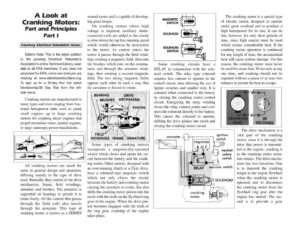
A Look at Cranking Motors: Part and Principles Part I Courtesy Electrical Rebuilders Assoc. Editors Note: This is the latest addition to the growing Electrical Rebuilder’s Association’s online Technical Library, avail- able to all ERA members. If you have not yet joined the ERA, come see what you are missing at www.electricalrebuilders.org. To sign up for a 30-day free trial select Membership/30 Day Trial from the left- side menu. Cranking motors are manufactured in many types and sizes ranging from frac- tional horsepower units used to crank small engines up to large cranking motors for cranking diesel engines that propel streamline trains, marine engines, or large stationary power installations. wound motor and is capable of develop- ing great torque. On cranking motors where high voltage is required, auxiliary shunt- connected coils are added to the circuit to slow down the top free running speed which would otherwise be destructive to the motor. As current enters the motor it passes through the field wind- ings creating a magnetic field, then into the brushes which ride on the commu- tator, and through the armature wind- ings, thus creating a second magnetic field. The two strong magnetic fields oppose each other in such a way that the armature is forced to rotate. BEARING DRIVE BRUSHES MECHANISM (sa 7 rz WINDINGS FRAME ARMATURE All cranking motors are much the same in general design and operation, differing mainly in the type of drive used. Basically, they consist of the drive mechanism, frame, field windings, armature and brushes. The armature is supported on bearings to permit it to rotate freely. All the current that passes through the field coils also travels through the armature. This type of cranking motor is known as a SERIES Some types of cranking motors incorporate a magnetically-operated switch which closes and opens the cir- cuit between the battery and the crank- ing motor. Other motors, designed with an over-running clutch or a Dyer drive, have a solenoid type magnetic switch which not only closes the circuit between the battery and cranking motor causing the armature to rotate, but also shifts the cranking motor pinion into the mesh with the teeth on the flywheel ring gear of the engine. When the drive pin- ion becomes engaged with the teeth of the ring gear, cranking of the engine takes place. MAGNETIC SWITCH SOLENOID SOLENOID SWITCH Some cranking circuits have a RELAY in conjunction with the sole- noid switch. The relay type solenoid requires less current to operate in the control circuit, thus allowing the use of lighter switches and smaller wire. It is actuated when connected to the battery by closing the cranking motor control circuit. Energizing the relay winding closes the relay contact points and con- nects the solenoid directly to the battery. This causes the solenoid to operate, shifting the drive pinion into mesh and closing the cranking motor circuit. The cranking motor is a special type of electric motor, designed to operate under great overload and to produce a high horsepower for its size. It can do this, however, for only short periods of time, since high current must be used which creates considerable heat. If the cranking motor operation is continued for any length of time, the accumulated heat will cause serious damage. For this reason, the cranking motor must never be used for more than 30 seconds at any one time, and cranking should not be repeated without a pause of at least two minutes to permit the heat to escape. ammeter «> = cranking : 5 motor = ignition switch The drive mechanism is a vital part of the cranking motor, since it is through the drive that power is transmit- ted to the engine, cranking it as the cranking motor arma- ture rotates. The drive mecha- nism has two functions. One is to transmit the cranking torque to the engine flywheel when the cranking motor is operated and to disconnect the cranking motor from the flywheel ring gear after the engine has started. The sec- ond is to provide a gear neutral safety switch