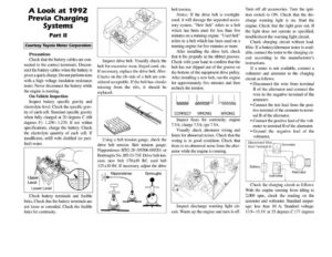
A Look at 1992 Previa Charging Systems Part Il Courtesy Toyota Motor Corporation Precautions Check that the battery cables are con- nected to the correct terminals. Discon- nect the battery cables when the battery is given a quick charge. Do not perform tests with a high voltage insulation resistance tester. Never disconnect the battery while the engine is running. On-Vehicle Inspection Inspect battery specific gravity and electrolyte level. Check the specific grav- ity of each cell. Standard specific gravity when fully charged at 20 degrees C (68 degrees F): 1.250—1.270. If not within specifications, charge the battery. Check the electrolyte quantity of each cell. If insufficient, refill with distilled (or puri- fied) water. Lower Level Check battery terminals and fusible links. Check that the battery terminals are not loose or corroded. Check the fusible links for continuity. Inspect drive belt. Visually check the belt for excessive wear, frayed cord, etc. If necessary, replace the drive belt. Hint: Cracks on the rib side of a belt are con- sidered acceptable. If the belt has chunks missing from the ribs, it should be replaced. Using a belt tension gauge, check the drive belt tension. Belt tension gauge: Nippondenso BTG-20 (95506-00020) or Borroughs No. BT-33-73F. Drive belt ten- sion: new belt 170+10 Ibf; used belt 125+10 Ibf. If necessary, adjust the drive Nippondenso U Borroughs belt tension. Notice: If the drive belt is overtight- ened, it will damage the separated acces- sory system. “New belt” refers to a belt which has been used for less than five minutes on a running engine. “Used belt” refers to a belt which has been used on a running engine for five minutes or more. After installing the drive belt, check that it fits properly in the ribbed grooves. Check with your hand to confirm that the belt has not slipped out of the groove on the bottom of the equipment drive pulley. After installing a new belt, run the engine for approximately five minutes and then recheck the tension. ss dasasay lnsaaah CORRECT WRONG WRONG Inspect fuses for continuity: engine 7.5A; charge 7.5A; ign 7.5A. Visually check alternator wiring and listen for abnormal noises. Check that the wiring is in good condition. Check that there is no abnormal noise from the alter- nator while the engine is running. Inspect discharge warning light cir- cuit. Warm up the engine and turn it off. Turn off all accessories. Turn the igni- tion switch to ON. Check that the dis- charge warning light is on. Start the engine. Check that the light goes out. If the light does not operate as specified, troubleshoot the warning light circuit. Check charging circuit without load. Hint: If a battery/alternator tester is avail- able, connect the tester to the charging cir- cuit according to the manufacturer’s instructions. If a tester is not available, connect a voltmeter and ammeter to the charging circuit as follows: ¢ Disconnect the wire from terminal B of the alternator and connect the wire to the negative terminal of the ammeter. ¢ Connect the test lead from the posi- tive terminal of the ammeter to termi- nal B of the alternator. ¢ Connect the positive lead of the volt- meter to terminal B of the alternator. ¢Ground the negative lead of the voltmeter. Disconnect Wire —— Ammeter from Terminal B = Alternator Soaecaenal Voltmeter | ai Check the charging circuit as follows: With the engine running from idling to 2,000 rpm, check the reading on the ammeter and voltmeter. Standard amper- age: less than 10 A; Standard voltage: 13.9-15.1V at 25 degrees C (77 degrees