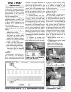
What Is RVC? By Mohammad Samii Regulated Voltage Control, or RVC, is the latest GM charging system intro- duced for automotive/light truck appli- cations since 2005. I will go over official OE explanations for the system high- lights later, but for beginners, let’s start with this brief introduction: Simply said, RVC is a charging sys- tem that the regulator’s set point is con- stantly changing, depending on what the PCM and related components have decided to do at a particular point of time. Fair enough? The OE explanation behind the RVC design principle can be summarized as follows: e A dynamic system of controlling the charging system voltage; ¢ It adjusts alternator’s output voltage based mainly on estimated battery temperature and battery’s state of charge (SOC) of around 80 percent; ¢ Improves fuel economy, extends bat- tery life…as is the claim! ¢ Comes in two basic versions, RVC, and Stand Alone RVC (SARVC); ¢ It has various modes of operation; eIt is also classified by being Generation II, III, IV, etc., depending how many modes are active in the system. The Basics Early alternators used for RVC sys- tems were mainly a Remy DR-44G or a Bosch internal fan series, but other brands such as Valeo and Denso are also y File Edt Settings View Window futemotive Help appearing in this system. Regardless of the alternator used, their regulator con- nector has only two pins, named “L” and “F’ terminals (Figure 1), even if the warning light on the instrument cluster has nothing to do with alternator’s “L” terminal and is driven by vehicle’s data bus. Here I will briefly explain the opera- tion of each terminal: “L” terminal, regardless of its name, has no connection to the “Alt Light,” but it receives a varying pulse-width modu- lated (PWM) signal that oscillates at 128 Hz (cycle per second) that varies between 0 to 4 volt in height. Just imagine that each change in the pulse-width value is a command for a new regulator set point, thus the system voltage setting changes based on the width of the signal on the L terminal. When measured by a voltmeter, the reading can obviously vary between 0 to 4 VDC, but in reality, in a typical vehicle idling in a moderate load, it reads about 3VDC. “F’ terminal is the feedback of the voltage regulator to the respective elec- tronic module which conveys the regula- a Ge Figure 1— The 2-Pin Connector of the RVC Alternator ‘=|Joe =] fx zBf+z0¥ =| Alsoy x[20 msfdiv =| [1 alec =p =] 80 ch Ac Frequency{Hz] ch &: DC voltage(my} ch B: Frequency(Hz} ch B: DC voltage(m¥y | Waiting for ADC Trigger [Auto >| |ch A>} [Rising | fo |Smy Figure 2— Scope Capture of “L” & “F” Terminals Waveform On-vehicle ee tor duty cycle and the load value. This is a 400 Hz signal, the same as any other CS or AD regulator. On-vehicle, its value changes between 3 to 10 VDC, depend- ing on the load and rpm. A scope capture of these two signals can be seen in Figure 2. Modules Involved Knowing that RVC can come in two basic versions; RVC or SARVC, here is a list of modules involved that one way or the other have something to do with the system. But here is a point worth mention- ing: Since RVC is varying the voltage set point but also wants to keep the battery’s state of charge (SOC) at 80 percent or better, then it also has to know the amper- age that is flowing in and out of the bat- tery. To do this, it needs some sort of cur- rent sensor that like a magnetic pickup, it is clamped over the battery’s negative cable. The double asterisk (**) on the fol- lowing list shows the modules that are also current sensors: 1. Battery Current Sensor (RVC)** (Figure 3) 2. Generator Battery Control Module (SARVC)**(Figure 4) 3. Body Control Module (BCM) 4. Instrument Panel Module (IPM) 5. Dash Integration Module (DIM) Figure 3 — Battery Current Sensor…RVC Figure 4 — Generator Battery Control Module…SARVC