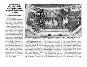
Examining 1993 to 2001 Villager/Quest Engine Electrical Systems Courtesy Haynes Publishing General Information The engine electrical systems include all ignition, charging and starting compo- nents. Because of their engine-related functions, these components are consid- ered separately from chassis electrical devices like the lights, instruments, etc. Be very careful when working on the engine electrical components. They are easily damaged if checked, connected or handled improperly. The alternator is driven by an engine drivebelt which could cause serious injury if your hands, hair or clothes become entangled in it with the engine running. Both the starter and alter- nator are connected directly to the battery and could arc or even cause a fire if mis- handled, overloaded or shorted out. Never leave the ignition switch on for long periods of time with the engine off. Don’t disconnect the battery cables while the engine is running. Correct polarity must be maintained when connecting battery cables from another source, such as another vehicle, during jump starting. Always disconnect the negative cable first and hook it up last or the battery may be shorted by the tool being used to loosen the cable clamps. H H H t H } i i t t t t i i = i aie LY ad sated Starting, charging and ignition system components: 1. Starter motor (not visible); 2. Battery; 3. Spark plugs and wires (front bank); 4. Distributor; 5. Ignition coil; 6. Power transistor; and 7. Alternator (not visible). Battery Check and Replacement Caution: Always disconnect the nega- tive cable first and hook it up last or the battery may be shorted by the tool being used to loosen the cable clamps. A battery cannot be accurately tested until it is at or near a fully charged state. Disconnect the negative battery cable, then the positive cable from the battery and perform the following tests: * Battery state of charge test—Visually inspect the indicator eye (if equipped) on the top of the battery. If the indicator eye is black in color, charge the battery. On batteries with removable caps (Nissan models) check the battery electrolyte. The electrolyte level should be above the upper edge of the plates. If the level is low, add distilled water. Do not overfill. The excess electrolyte may spill over during periods of heavy charging. Test the specific gravity of the elec- trolyte using a hydrometer. Remove the caps and extract a sample of the electrolyte and observe the float inside the barrel of the hydrometer. Follow the instructions from the tool manufacturer and determine the exact condition of the solution for each cell. A normal battery will indicate approximately 1.270 (green zone). If the electrolyte content is too low (red zone), charge the battery. ¢ Open voltage circuit tes:—Using a digital voltmeter, perform an open voltage circuit test. Note: The battery’s surface charge must be removed before accurate