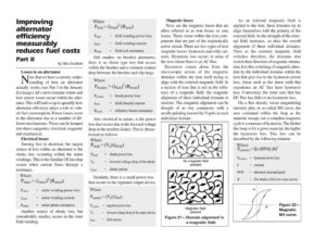
Improving alternator efficiency measurably reduces fuel costs Part Il By Mike Bradfield Losses in an alternator N* that we have a cursory under- standing of how an alternator actually works (see Part I in the January Exchange), let’s next examine where and how power losses occur within the alter- nator. This will lead us up to quantify how alternator efficiency plays a role in vehi- cle fuel consumption. Power losses occur in the alternator due to a number of dif- ferent mechanisms. These can be lumped into three categories: electrical, magnetic and mechanical. Electrical losses Turning first to electrical, the largest source of loss within an alternator is the ohmic loss occurring within the stator windings. This is the familiar i°R loss that occurs when current flows through a resistance. Where P stator = (stator) (Rstator) Prtstor stator winding power loss istator = stator winding current Ramee = stator phase resistance Another source of ohmic loss, but considerably smaller, occurs in the rotor field winding. Where Prieta = (inieta) (Reta) Prieta = field winding power loss ifiela = field winding current Rgieta = field coil resistance Still smaller, on brushed alternators, there is an ohmic type loss that occurs within the brushes and a resistant contact drop between the brushes and slip rings. Where a) Preushes = (neta) (Roush) Phrushes brush power loss ificld = field (brush) current Rorush effective brush resistance Also electrical in nature, is the power loss that occurs due to the forward voltage drop in the rectifier diodes. This is charac- terized as follows: Where P diode = (Va) (Idiode) Puiode diode power loss Va = forward voltage drop of the diode igiode = diode current Similarly, there is a small power loss that occurs in the regulator output device. Where Pregulator = (Va) (ifeta) Pregulator = regulator power loss Va = forward voltage drop of the output device ifictd = field current Magnetic losses Next, are the magnetic losses that are often referred to as iron losses or core losses. These occur within the iron com- ponents that are part of the magnetically active circuit. There are two types of iron magnetic losses: hysteresis and eddy cur- rents. Hysteresis loss occurs in areas of the iron where there is an AC flux. Hysteresis comes about from the microscopic action of the magnetic domains within the iron itself trying to align with the external magnetic field. In a section of iron that is not in the influ- ence of a magnetic field, the magnetic alignment of these individual domains is random. This magnetic alignment can be thought of as tiny compasses with a needle pointing toward the N pole in each individual domain. No magnetic field present Magnetic field present Figure 21— Domain alignment in a magnetic field. As an external magnetic field is applied to the iron, these domains try to align themselves with the polarity of the external field. As the strength of the exter- nal field increases, so does the overall alignment of these individual domains. Then as the external magnetic field switches direction, the domains also switch their direction of magnetic orienta- tion. Itis this switching of magnetic direc- tion by the individual domains within the iron that give rise to the hysteresis power loss. Areas such as the stator teeth that experience an AC flux have hysteresis loss. Conversely, the rotor core that has DC flux has little or no hysteresis loss. On a flux density versus magnetizing intensity plot, or so-called BH curve, the area contained within the loop as the material sweeps out a complete magnetic cycle is a measure of hysteresis. The thicker this loop is for a given material, the higher the hysteresis loss. This loss can be described by the following relation: Where – Physteresis = hysteresis power loss k = constant RPM ~— = _ alternator rotational speed B = flux density of the iron cross section H Figure 22— Magnetic BH curve.