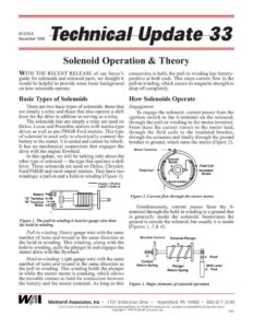
87-278-5 November 1996 Solenoid Operation & Theory WITH THE RECENT RELEASE of our buyer’s guide for solenoids and solenoid parts, we thought it would be helpful to provide some basic background on how solenoids operate. Basic Types of Solenoids There are two basic types of solenoids: those that are simply a relay and those that also operate a shift lever for the drive in addition to serving as a relay. The solenoids that are simply a relay are used on Delco, Lucas and Prestolite starters with inertia-type drives as well as pre-PMGR Ford starters. This type of solenoid is used only to electrically connect the battery to the starter. It is sealed and cannot be rebuilt. It has no mechanical connection that engages the drive with the engine flywheel. In this update, we will be talking only about the other type of solenoid — the type that operates a shift lever. These solenoids are used on Delco, Chrysler, Ford PMGR and most import starters. They have two windings: a pull-in and a hold-in winding (Figure /). Heavy = Pull-in Light = Hold-in Battery > MC] | “S” Terminal > al “R” Terminal — =h Figure 1. The pull-in winding is heavier gauge wire than the hold-in winding. Pull-in winding: Heavy-gauge wire with the same number of turns and wound in the same direction as the hold-in winding. This winding, along with the hold-in winding, pulls the plunger in and engages the starter drive with the flywheel. Hold-in winding: Light-gauge wire with the same number of turns and wound in the same direction as the pull-in winding. This winding holds the plunger in while the starter motor is cranking, which allows the movable contact to hold the connection between the battery and the motor terminal. As long as this connection is held, the pull-in winding has battery- positive at both ends. This stops current flow in the pull-in winding, which causes its magnetic strength to drop off completely. How Solenoids Operate Engagement To engage the solenoid, current passes from the ignition switch to the S-terminal on the solenoid, through the pull-in winding to the motor terminal. From there the current travels to the motor lead, through the field coils to the insulated brushes, through the armature and finally through the ground brushes to ground, which turns the starter (Figure 2). Motor Terminal Figure 2. Current flow through the starter motor. Simultaneously, current passes from the S- terminal through the hold-in winding to a ground that is generally inside the solenoid. Sometimes the ground is outside the solenoid, but usually it is inside (Figures 1, 2 & 4). Movable Contact Y Solenoid Plunger Contact Return Spring Shift Lever <— Fork Plunger Return Spring Figure 3. Major elements of solenoid operation / fa | Wetherill Associates, Inc.- 1101 Enterprise Drive + Royersford, PA 19468 +» 800-877-3340 Care is taken to ensure the accuracy of information presented here, but Wetherill Associates, Inc., assumes no responsibility for possible errors. Copyright © 1996 Wetherill Associates, Inc. 5302 Technical Update 33 page 2 These windings work together to create a very strong magnetic field that pulls in the plunger. The plunger is attached to a shift lever, which in turn moves the drive into engagement with the flywheel. As the drive is engaging the flywheel, the plunger continues to push the movable contact so it makes the connection between the battery and motor terminals. This causes the starter motor to turn and crank the engine (Figure 3). If the solenoid has an active R-terminal, the movable contact closes this connection as well. In early ignition systems, the R-terminal serves as an output terminal that bypasses the ignition resistor. In later systems, it is used as a signal that the engine is in cranking mode. Current flow during engagement Ground Hold-in ) Motor Figure 4. Current flow in pull-in and hold-in wind- ings during solenoid engagement. When the shift lever moves the drive toward engagement with the flywheel, the drive often does not engage, but hits the flywheel teeth head- on. When this happens, an indexing mechanism in the drive and/or shift lever allows the plunger to continue to move so it closes the solenoid con- tacts. This causes the starter motor to turn, which in turn allows the drive to become aligned prop- erly for engagement with the flywheel. There are three main kinds of indexing mechanisms: spring-and-collar type, spring- loaded-gear type and positorque type. In a spring-and-collar type, the shift lever pushes on a collar, which pushes on a spring, which in turn pushes the drive toward engage- ment with the flywheel. If the teeth do not engage, the spring collapses, allowing the plunger to continue to move and close the sole- noid contacts. Once the drive teeth are aligned with the flywheel teeth, the spring pushes the drive into engagement (Figure 5). In the case of a spring-loaded-gear type of indexing mechanism, if the drive does not engage with the flywheel, the spring behind the gear collapses so the gear can move back on the drive shaft. This allows the contacts to close and the starter motor to turn. Once the teeth are Figure 5. Spring-and-collar type indexing mechanism. aligned, the spring engages the drive with the flywheel. With this type of mechanism it is very important that the drive moves freely along the splines of the shaft (Figure 6). Positorque indexing mechanisms have a pinion that moves along a spiral set of splines inside the drive. The pinion turns as it is pushed into the drive body, which allows the teeth to align themselves. Once the teeth are aligned, the pinion moves back out and the drive continues to move on the armature until the drive teeth Figure 6. Spring-loaded gear type indexing mechanism. become fully engaged with the flywheel. The plunger then closes the solenoid contacts and current flows to the starter motor. The Lucas M50 has a unique method of indexing. This starter has a separate (4th) coil and a solenoid with an additional set of contacts that allow current to flow only in this 4th coil. This allows the armature to turn slowly and the drive to engage properly with the flywheel. After full engagement, the other contacts close and the starter cranks with its full power. Disengagement When the ignition switch is released, current stops flowing to the S-terminal, but until the movable contact breaks the circuit, current con- tinues to flow from the battery terminal through the contact disk to the motor terminal, back through the pull-in winding to the S-terminal and through the hold-in winding to ground.