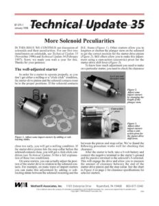
87-375-1 January 1998 More Solenoid Peculiarities IN THIS ISSUE WE CONTINUE our discussion of solenoids and their peculiarities. For our first two installments on solenoids, see Technical Update 33 (November 1996) and Technical Update 34 (February 1997). Sorry we made you wait a year for this. Thanks for your patience. The well-adjusted starter In order for a starter to operate properly, so you don’t get either a milling or a “click-click” condition, the starter-drive pinion and the solenoid contacts must be in the proper positions. If the solenoid contacts Figure 1. Adjust some import starters by adding or sub- tracting shims. close too early, you will get a milling condition. If the starter-drive pinion hits the stop collar before the solenoid contacts close, you will get a click-click con- dition (see Technical Update 34 for a full explana- tion of these two conditions). On some starters, you can actually adjust the posi- tion of the starter drive in relation to the solenoid con- tacts. For example, on many types of import starters you can make this adjustment by adding or sub- tracting shims between the solenoid mounting and the D.E. frame (Figure 1). Other starters allow you to lengthen or shorten the plunger stem on the solenoid to get the correct position for the starter-drive pinion (Figure 2). Still others allow you to make this adjust- ment using a cam-action (eccentric) pivot for the starter-drive shift lever (Figure 3). To know how much adjustment you need to make on a particular starter, you need to check the clearance Figure 2. Adjust some import starters by changing the length of the plunger stem. ~~ ~ Cam-action – pivot + h Figure 3. Adjust other import starters using a cam- action pivot for the starter-drive shift lever. between the pinion and stop collar. We’ve found the following procedure works well for checking that clearance: After the starter is built, take a 6-volt battery and connect the negative terminal to the starter’s ground and the positive terminal to the solenoid’s S-terminal. This will engage the drive and allow you to measure the amount of clearance between the end of the starter-drive pinion and the stop collar. See the chart in Figure 4 on page 2 for clearance specifications for selected starters. Wy Wl Wetherill Associates, Inc. 1101 Enterprise Drive Royersford, PA 19468 800-877-3340 Care is taken to ensure the accuracy of information presented here, but Wetherill Associates, Inc., assumes no responsibility for possible errors. Copyright © 1998 Wetherill Associates, Inc. 5584 Technical Update 35 page 2 Pinion Adjustments Lucas elco (Distance between pinion and | (Distance between pinion and D.E. thrust washer/stop collar) housing) M50 & M127 .015 – .025 | 40MT M35G 005-.015 | 4amT & 23/64 + 1/82 M418G 005-.015 50MT Y 360.031 M45G, M .005 – .015 (roller clutch style) M45G .020 – .030 (S.I.D. clutch disc style) Figure 4. For Bosch, Mitsubishi, Nippondenso and Hitachi solenoids, adjustment specifications vary for each make and model. Refer to your Mitchell manual or OE service manuals for these specifications. WARNING: 1. Do not make a connection to the battery terminal on the solenoid. 2. Do not use a 12-volt battery for this test. With a 12-volt battery the solenoid will draw twice the amount of current, which will cause it to heat up excessively and pos- sibly destroy the solenoid windings. 3. Finally, if the armature starts turning when you conduct this test, you should ground the motor terminal of the solenoid to prevent the armature from turning. Lucas MS0 starters have a unique set of prob- lems when they are not properly adjusted because of the way they index the starter drive with the flywheel. On these starters, if the drive pinion hits the flywheel but doesn’t engage, a secondary set of contacts in the solenoid allows current to flow only in the fourth coil of the field coils. The arma- ture then turns slowly, allowing the drive pinion to align itself with the flywheel. Once the drive is engaged with the flywheel, the primary sole- noid contacts also close, allowing current to flow to the other three field coils as well as the fourth coil, so the starter cranks properly. If the starter is out of adjustment so that when the drive pinion hits the flywheel the secondary set of contacts will not close, you will get a click- click condition when the starter is on the engine —even though it checks fine on the test bench. If, on the other hand, the starter is out of adjustment so the drive pinion hits the stop collar before the primary set of contacts closes, the starter will be operating only on the fourth field coil and this coil will burn up. Nippondenso industrial starters On some Nippondenso starters used on indus- trial equipment, the starter drive may stay engaged with the flywheel after the start switch has been returned to the run position. However, the starter operates properly on the test bench. Shunt Coils in Starter £ Hold In Grou nd Switch Pull In Motor Figure 5. Some Nippondenso industrial starters have two shunt coils connected in parallel with the hold-in winding. This can sometimes be caused by a battery that is insufficiently charged. But there can be another reason for this problem. These starters have two shunt coils in the field case that are connected in parallel with the solenoid hold-in winding (Figure 5). If the shunt coils have a problem with high resistance (causing low amp flow) or if they are shorted or grounded (causing high amp flow), the solenoid will be unbalanced. As a result, the plunger will not return properly, which will keep the drive engaged with the flywheel. Figure 6. For a solenoid balance test, connect lead A with S-terminal A; connect lead B and solenoid case B to neg- ative. Field coils should be in the case and the case con- nected to negative. To find the source of this problem you can do a solenoid balance test after you have taken the starter apart. First, connect one shunt-coil lead to the S-terminal (A to A, as shown in Figure 6). Then connect battery-positive to the solenoid motor terminal (C in Figure 6). Finally, connect