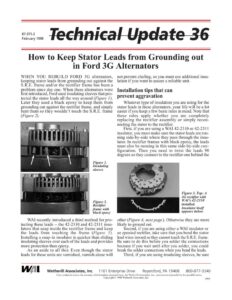
87-375-2 February 1998 How to Keep Stator Leads from Grounding out in Ford 3G Alternators WHEN YOU REBUILD FORD 3G alternators, keeping stator leads from grounding out against the S.R.E. frame and/or the rectifier frame has been a problem since day one. When these alternators were first introduced, Ford used insulating sleeves that pro- tected the stator leads all the way around (Figure /). Later they used a black epoxy to keep them from grounding out against the rectifier frame, and simply bent them so they wouldn’t touch the S.R.E. frame (Figure 2). Figure 1. Insulating sleeves Figure 2. Rectifier frame with black epoxy WAI recently introduced a third method for pro- tecting these leads — the 42-2310 and 42-2311 insu- lators that snap inside the rectifier frame and keep the leads from touching the frame (Figure 3). Installing a snap-in insulator is quicker than sliding insulating sleeves over each of the leads and provides more protection than epoxy. As an aside to all this: Even though the stator leads for these units are varnished, varnish alone will not prevent chafing, so you must use additional insu- lation if you want to assure a reliable unit. Installation tips that can prevent aggravation Whatever type of insulation you are using for the stator leads in these alternators, your life will be a lot easier if you keep a few basic rules in mind. Note that these rules apply whether you are completely replacing the rectifier assembly or simply recon- necting the stator to the rectifier. First, if you are using a WAI 42-2310 or 42-2311 insulator, you must make sure the stator leads are run- ning side-by-side where they pass through the insu- lator. In rectifier frames with black epoxy, the leads must also be running in this same side-by-side con- figuration. Then you need to twist the leads 90 degrees so they connect to the rectifier one behind the Figure 3. Top: A 3G rectifier with WAI’s 42-2310 installed. Insulator itself appears below. other (Figure 4, next page). Otherwise they are more likely to ground out. Second, if you are using either a WAI insulator or an epoxied rectifier, take care that you bend the stator lead wires inward so they cannot touch the S.R.E. frame. Be sure to do this before you solder the connections because if you wait until after you solder, you could break the solder connections when you bend the leads. Third, if you are using insulating sleeves, be sure yf Wl Wetherill Associates, Inc. 1101 Enterprise Drive Royersford, PA 19468 800-877-3340 Care is taken to ensure the accuracy of information presented here, but Wetherill Associates, Inc., assumes no responsibility for possible errors. Copyright © 1998 Wetherill Associates, Inc. 5999 Technical Update 36 page 2 the insulation covers the leads anywhere they might chafe on either the rectifier assembly or S.R.E. frame. the other 8d Figure 4. Run stator leads side-by-side as they come up through the rectifier frame, then twist them 90 degrees so they connect to the rectifier one behind the other. Ww Soldering tips After you crimp the stator leads in place but before you begin to solder them to the rectifier, be sure to bend down the wing tabs that protrude from the rectifier. This will keep the tabs from grounding out against the S.R.E. frame (Figure 5). You ‘llalso see that the stator-connection area is bent upward at the connection edges. These bent edges assure a better solder connection when the rectifiers are wave soldered. Wave soldering involves turning the rectifier/stator assembly upside down and passing it over a tray of molten solder, to solder all the stator leads at one time. Figure 5. Bend down the wing tabs after you crimp the stator leads in place. When you hand solder these connections, we recommend that you turn the rectifier-stator assembly upside down. That way the solder will puddle on the bottom side of the connection and won’t run down the stator leads. Finally, make sure you trim the leads after you solder them. If they extend too high above the rectifier bridge they can ground out on the S.R.E. frame. Installing the S.R.E. frame When you’re installing a rectifier, it’s impor- tant to note what style S.R.E. frame you have (early- or late-style) because this will affect the way you reassemble the alternator. On early-style S.R.E. frames, the hole for the battery-terminal insulator is flat on two sides. If you are using one of these S.R.E. frames, the bat- tery-terminal insulator is installed after the alter- nator is assembled. fi | : a sail ana i Ps Figure 6. Early-style S.R.E. frame on left. Late-style on right. Figure 7. Battery-terminal insulator on left is used with early-style S.R.E. frame. Insulator and battery-terminal nut on right are used with late-style S.R.E. frame. However, if you are using a late-style S.R.E. frame (hole for the battery-terminal insulator has a point on two sides), the insulator must be snapped into the S.R.E. frame before the alter- nator is assembled and you must install a battery- terminal extended hex nut on the rectifier before you install the S.R.E. frame (Figures 6 & 7).