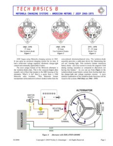
TECH BASICS G MOTOROLA CHARGING SYSTEMS – AMERICAN MOTORS / JEEP 1965-1975 1965 – 1970 1965 – 1970 1971 – 1975 37 Amp 55 Amp 37-55 Amp One Isolation-diode Two Isolation Diodes Diode Trio Figure 1 Figure 2 Figure 3 AMC began using Motorola charging systems in 1965. It was quite an advanced charging system for its time. It had a solid-state voltage regulator, electronic charge-light control and externally replaceable brushes. The most unique feature of the Motorola alternator is the isolation-diode plate. This is the crescent-shaped plate (usually red or blue) that mounts to the SRE housing of the alternator. What’s it for? Here’s a quote from a 1968 Motorola sales brochure. “This Motorola feature incorporates semiconductors (silicon diodes) rather than the @®0000 IGNITION SWITCH > CHARGE LIGHT ORANGE REGULATOR GREEN ISOLATION DIODE TERMINAL conventional electromechanical relay. The isolation-diode assembly provides a solid-state device for illuminating the tell tale warning light. This exclusive feature minimizes battery drain – uses less current to excite the magnetic field during starting operation as compared to alternators not having this feature.” As you can see from Figure 4, the isolation-diode keeps battery current from feeding back into the charge-light and voltage regulator circuits. A more detailed explanation of the isolation-diode functions will be found in the sections 1965 Only and 1966 – 1970. ALTERNATOR AUX Figure 4 Alternator with ISOLATION-DIODE 03/2004 Copyright © 2004 Wesley S. Grueninger – All Rights Reserved Page | TECH BASICS G MOTOROLA CHARGING SYSTEMS – AMERICAN MOTORS / JEEP 1965-1975 #€ Battery OOCOO0O00 | 3% Ignition Switch =0| %% Charge-Light # Voltage Regulator ~ 3 Isolation Plate ty i% Alternator Wire Codes RED: BATT + ORANGE: AUX GREEN: FIELD BLACK: GROUND RED Figure5 1965 Wiring Diagram 1965 Only 1965 was the first year AMC used the Motorola charging system. Two alternator capacities were available – 37 amps for cars without air conditioning and 55 amps for cars with air conditioning. The 1965 charging system is unique in that it uses a three-wire solid-state voltage regulator. All later AMC vehicles use a four-wire solid-state voltage regulator. The isolation-diode was new in 1965. The purpose of the isolation-diode is to provide a means of controlling the charge light without using an electromechanical relay. Here’s how it works.: 1) When the engine is off, the isolation-diode “isolates” the current present at the alternator BATT+ terminal. It blocks current from feeding back through the AUX terminal. Without the isolation-diode, current from the battery would follow the orange charge-light wire to the voltage regulator, and the charging system would always be on. In fact, this is what happens when an isolation-diode has a shorting-type failure. 2) When the ignition is turned to the run position, current flows from the battery > through the ignition switch = through the charge indicator light and is directed by the voltage regulator, to the rotor coil. The current finds a ground path at the negative brush inside the alternator and the charge-indicator bulb lights up. 3) When the engine starts, the alternator produces current which is split at the isolation-diode plate and follows two paths. Most of the current passes through the BATT+ terminal to charge the battery and run accessories. About 3 amps of the current goes out the AUX terminal along the orange wire to the voltage regulator and the charge-indicator light. The voltage regulator uses this current to power the rotor field. The charge-indicator light goes out, since it has the same voltage on either side of the filament and no current can flow. USE THE CORRECT REGULATOR Regulators used on alternators with isolation-diodes are set 0.8 volts higher to compensate for the voltage drop in the isolation-diode. A regulator used with an isolation-diode equipped alternator should not be used with a diode-trio equipped alternator. The higher voltage setting will cause overcharging and result in high water loss and shorter battery life. Conversely, if a regulator designed for a diode-trio equipped alternator is used with an isolation-diode equipped alternator it will result in undercharging and shorter battery life. 03/2004 Copyright © 2004 Wesley S. Grueninger – All Rights Reserved Page 2 TECH BASICS G MOTOROLA CHARGING SYSTEMS – AMERICAN MOTORS / JEEP 1965-1975 #€ Battery 1966 – 1970 ie Ignition al In 1966, AMC made a small change to the EC 3 Charge-Light Motorola charging system. A fourth wire (yellow) was added to the voltage regulator. This yellow wire Ds Voltage Regulator conducts full battery voltage to the regulator when the @O0O0000 1% Isolation Plate ignition key is in the run position. It’s called an Excitation wire. It improves low-speed charging 3% SF Alternator system turn-on and allows more precise monitoring of 7 the battery state-of-charge. wre Codes BATT + Other than the addition of the Excitation wire, the ORANGE: AUX 1966 – 1970 Motorola charging system functions like FIELD the 1965 Only system. GREEN: : EXC GROUND RED Figure6 1966-1970 Wiring Diagram 03/2004 Copyright © 2004 Wesley S. Grueninger – All Rights Reserved Page 3