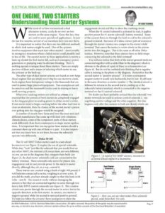
ELECTRICAL REBUILDER’S ASSOCIATION — Technical Document $S201903A www.electricalrebuilders.org ONE ENGINE, TWO STARTERS hile most of us have encountered a dual alternator system, rarely do we ever see two starters on the same engine. None-the-less, they are used in some specialized applications. In just the last few months, several of our members have run into them. It is important to realize that there are two different methods in which dual starters might be used. One of the systems involves equipment that must start when needed – most notably in emergency situations where a failed starter could possibly lead to loss of life. The second starter in those applications is merely a back-up should the first starter fail, such as in emergency power generation or pumping water to alleviate flooding. There is nothing special or unique about these starters. There are simply just two of them and a means of selecting which starter to use, the primary or the back-up. The other type of dual starter systems are found on very large diesel engines that are simply too to big for one starter to crank. Such engines have horsepower ratings in the thousands that are used to power huge pieces of equipment. Two examples are rail locomotives and the mammoth trucks used in mining or heavy earth-moving projects. When two cranking motors are utilized as a team, it is essential that the pinions of both starters be completely engaged in the ring gear prior to sending power to either starter’s motor. If one starter were to begin cranking before the other had time to clear an abutment, then the chance of the second starter’s pinion ever getting into the ring gear would be marginal. A number of circuits have been used over the years and each different manufacturer has come up with their own solutions. Almost always, some of the component parts of these starters work differently than their counterparts in single starter applica- tions. It is important that you recognize these starters should a customer show up with one of them or a pair. It is also import- ant that you know how to test them, because the solenoids operate very differently. Delco 50-MT The 32 volt 50MT Delco starters used to crank diesel locomotives (see Figure 1) employ the use of special solenoids. While they “look” just like the solenoid that you would find on any other 50MT, the internal coil connections are very different. As you can see in the diagrams that compare them both (see Figure 2), the dual starter solenoid’s coils are connected to the battery terminal. These solenoids only move the pinion into engagement and do not provide power to the starter’s motor directly, although they do, in a way, control it. These starters are cranked using a bank of eight 300 pound, 8 volt batteries connected in series, weighing in at over a ton. If you did the math, you have already caught on that this bank is 64 volts – not 32. The reason it works without damaging the starters is that they are connected together in series through two heavy duty DPST control solenoids (see Figure 3). This creative circuit runs power through the second starter in series, but in the opposite direction as the first starter. In essence, one starter is negative ground while the second is operated positive ground! To help you follow the circuits I have used green to show the seca BY BOB THOMAS engagement circuit and blue to show the cranking circuit. When the #1 control solenoid is activated to start, it applies positive power the #1 starter solenoid’s battery terminal. Some of the current flows on through the hold-in coil to the solenoid’s ground terminal. But most of it takes a lower path of resistance through the starter’s motor via a jumper to the starter’s field terminal. That causes the motor to rotate slowly as the pinion moves into the ring gear. This is the same as all other Delco starters. However, note that these starters have no field straps connecting the solenoid to the field terminal! You will also notice that both of the starter ground studs are connected together with a cable (blue in the diagram) which is obvious in the photo of a pair of these on a locomotive (see Figure 4). But do not be confused into thinking that a negative cable is missing in the photo or the diagram. Remember that the second starter is “positive ground”. If it were a permanent magnet starter it would turn backwards, but it’s not. It will turn in the same direction as starter number 1. The identical circuit is followed in reverse in the second starter, ending up at the solenoid’s battery terminal, which is connected to the negative terminal on the #1 control solenoid. No doubt you have probably noticed that the solenoids’ two motor terminals are used to activate control solenoid 2, one supplying positive voltage and the other negative. But this happens only after the contacts in both are closed, which can Figure 1 – A team of 32v 50MT starters, mounted on a Detroit Diesel engine in a locomotive. Dual Starter Single Starter oy (em Pull-in Yi 1G” F 2 oS Figure 2 – Here you can see what makes these solenoids special, aside from their 32v coils. An ERA Publication. ©2019, Electrical Rebuilder’s Association. All rights reserved. No portion of the guide may be reproduced in Page 1 any way, or stored in any electronic retrieval system without the prior written consent of the Electrical Rebuilder’s Association.