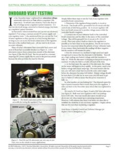
ELECTRICAL REBUILDER’S ASSOCIATION — Technical Document CS201702B www.electricalrebuilders.org ONBOARD VSAT TESTING BY GENE KAISER n the December issue I explained how saturation voltage, commonly referred to as Vsat, affects a regulator’s life expectancy. To refresh your memory, Vsat is the drop or loss of voltage across a regulator’s power transistor. It is that lost electrical energy, converted to thermal energy, that heats up a regulator’s power transistor. In that article I demonstrated how you can test any electronic regulator’s Vsat using a constant current DC power supply and your regulator tester. I also mentioned that you can test the Vsat of some regulators as they operate on a functioning alternator – so long as you can access the brush connections to the regulator. Not only is this method fairly easy – all you need to do it is an accurate voltmeter. Many of today’s alternators have removable back covers and most of those have accessible brushes (see Figure 1). A few alternators expose those connections outside of the alternator (see Figure 2) like this 3G Ford. You do not need to a constant amperage DC power supply like we used in the previous article because the rotor provides the load for this test. Figure 1 – The brush connections of this 11SI are easily accessible for testing the regulator’s Vsat. Figure 2 – Ford 2G and 3G alternators are very easy to test Vsat, even on the vehicle in many applications. Simply follow these steps to test the Vsat of any regulator with accessible brush connections: 1. Determine if the regulator being tested is A-circuit or B-circuit. One brush will be grounded if it is B-circuit with the control side of field being positive. An A-circuit regulator will have one brush connected to positive voltage source while the controlled brush is negative. 2. Connect one of your voltmeter leads to the controlled brush connection and the other to the source of the controlled voltage. That will be ground if it is A circuit or B+ if it is B circuit. Place your meter’s leads as close to the regulator as possible as we have done in our test photos. You do not need to become too concerned about the polarity of your voltmeter leads. It you connect them backwards the reading will show negative but the numbers will remain the same. 3. Run the alternator at a medium to high speed and apply enough load to insure that the alternator is full fielded. You will see a high reading near battery voltage until the transistor is fully-on. While the alternator is charging at that point enough to maintain 14 volts, the field is actually off most of the time. 4. As the load nears the capacity of the alternator, the voltage on the meter will begin to drop rapidly. At this point, watch your battery voltage and output amperage. On most modern alterna- tors, you will need a load that exceeds the unit’s rated output before the alternator becomes full-fielded. Output voltage should be kept above 12.6 volts but in most cases you will need to get near or below 13 volts to insure that the power transistor is fully-on. So what number are you looking for? That depends upon the type of power transistor that is inside that particular regulator. I refer you back to the December issue where that was explained in detail. We tested a 3G Ford (see Figure 3) anda GM Valeo alternator (see Figure 4). Both were new regulators with Vsat readings below 0.50 volts. Most late model alternators should not go above one volt when heated up to operating temperature. However, I will reiterate that there is no better test than this to establish the reliability of any electronic regulator. I highly advise that use this test when reclaiming a regulator. Gene Kaiser is Quality Control and Technical Manager for Regitar-USA in Montgomery, AL. An ERA Publication. ©2017, Electrical Rebuilder’s Association. All rights reserved. No portion of the guide may be reproduced in Page 1 any way, or stored in any electronic retrieval system without the prior written consent of the Electrical Rebuilder’s Association. ELECTRICAL REBUILDER’S ASSOCIATION — Technical Document CS201702B www.electricalrebuilders.org ONBOARD VSAT TESTING Figure 3 – The Vsat on this aftermarket 3G regulator is well within limits at 0.38 volts. Figure 4 – The Vsat of this new GM/Valeo regulator is 0.46 volts, about what you would expect from a healthy regulator. An ERA Publication. ©2017, Electrical Rebuilder’s Association. All rights reserved. No portion of the guide may be reproduced in Page 2 any way, or stored in any electronic retrieval system without the prior written consent of the Electrical Rebuilder’s Association.