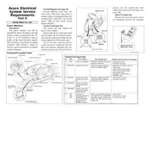
Acura Electrical System Service Requirements Part Il Honda Motor Co., Ltd. Power Windows Description The power windows can still be operated for about 10 minutes after the ignition switch is turned from the “II” to the “I” or “O” position as long as neither of the doors has been opened. This provides a convenience to parked occupants while offering a degree of security against unwanted or accidental window operation. Circuit Diagram (See page 16) Several different wires have the same color. They have been given a number suffix to distinguish them (for example YEL 1| and YEL 2 are not the same). “DN” in the switch circuit denotes DOWN. Control Unit Input Test The control unit only controls the driver’s door window. Remove the driver’s door trim panel and disconnect the 4-P and 6-P connec- tors from the control unit. Make the fol- lowing input tests at the harness pins. To test the unit, keep the driver’s switch connector connected with the door wire harness. Recheck the con- nections between the 4-P and 6-P con- Component Location Index R, REAR MOTOR POWER WINDOW RELAY UNDER-HOOD RELAY BOX RELAY BRACKET (Located under dash, left side) POWER WINDOW CONTROL UNIT KEY-OFF TIMER CIRCUIT (in the integrated control unit) R. REAR SWITCH R. FRONT DOOR SWITCH / DRIVER’S MOTOR CONTROL UNIT WHT/YEL BLK BLK/GRN RED/GRN BLK BLU View from wire side nectors, and the control unit, then replace the control unit if all input tests prove OK. Driver’s Switch Test Remove the door trim panel. Check for continuity between the terminals View from wire side R. FRONT MOTOR L. REAR SWITCH 2 | WHT/YEL Under all conditions. Ignition switch ON. Control Unit Input Test No. Wire Test condition Test: desired result should be continuity. Check for continuity to ground: Possible cause (if result is not obtained) * Poor ground (G15). + An open in the wire. Check for voltage to ground: should be battery voltage. L. REAR MOTOR Ignition switch ON and driver’s switch UP. Ignition switch ON and driver’s switch DOWN. Check for voltage to ground: should be battery voltage as the switch is turned. 3} BLK/YEL L. FRONT DOOR SWITCH 4 | BLK/GRN 5 | RED/GRN 6 BLU and BLK ! Ignition switch ON and driver’s switch DOWN (AUTO). + Blown No, 21 (40 A) or No. 12 (20 A) fuse. + Faulty power window relay. * Faulty key-off timer system. * Poor ground (G6). * An open in the WHT/YEL or WHT/BLK wire. * Faulty driver’s switch. + An open in the wire. Connect the WHT/YEL terminal to the RED/YEL ter- minal, and the BLK terminal to the RED/BLU terminal. motor runs. | Check for resistance between the BLK/YEL? and WHT/RED? terminals: should indicate be- | tween 20—50 ohms as the i + Faulty pulser, * Faulty driver’s motor. * An open in the wire.