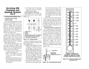
Servicing GM Charging and Starting Systems Part Il Courtesy General Motors Corp. Charging System Testing Battery Testing Note: All testing procedures used in this article are designed for use with a charging/starting system tester con- taining a variable load test (carbon pile) and a hand held volt-ohmmeter. Follow the instructions supplied by the manufacturer of the particular test equipment being used when perform- ing the tests outlined here. Tests that should be performed to determine the condition of the battery are the Capacity Test (load test), the Hydrometer Test (state of charge) and the Open Circuit Voltage Test (state of charge). Perform these tests as outlined to aid in battery diagnosis. Note: Perform the Hydrometer Test only when checking a battery with removable cell caps. If testing shows the battery to be in good condition but dis- charged, check for the following: 1.A vehicle accessory that stays on with the vehicle shut off. 2. There was extended slow-speed driving with many accessories turned on. 3. The vehicle electrical load is more than the alternator output, particu- larly with the addition of aftermar- ket equipment. 4. An alternator with an output rating lower than what was originally installed on the vehicle. Charge Indicator (Delco Eye) Delco batteries use an indicator eye to monitor the battery’s state of charge (Figure 1-18). A 1. GREEN DOT 2. DARK 3. CLEAR A. 65% OR ABOVE STATE OF CHARGE B. BELOW 65% STATE OF CHARGE C. LOW LEVEL ELECTROLYTE Figure 1-18—Charge Indicator Refer to the following steps to deter- mine battery condition by looking at the charge indicator eye: 1. GREEN DOT VISIBLE: The state of charge is 65 percent or more of the full charge. Under this condi- tion the battery may be load tested. 2. DARK; GREEN DOT NOT VISI- BLE: The state of charge is below 65 percent. Charge the battery until the green dot appears. (To make the green dot appear after charging, shake the battery slightly or tap the eye to remove any bubbles.) . CLEAR OR LIGHT YELLOW: The fluid level has dropped below ww the bottom of the hydrometer. This can be caused by a broken case, tipping of the battery, extended use or overcharging because of a prob- lem in the electrical system. Check the charging system and replace the battery. Caution: When the dot has returned to green, stop the charge. Allow battery to cool, and proceed with the load test as outlined under “Battery Testing” here. If electrolyte seeps from the vent(s), stop the charge and allow the battery to cool before proceeding. Hydrometer (State of Charge) Test Use a hydrometer to check the spe- cific gravity of all battery cells (Figure 1-19). In order to get an accurate inter- pretation of hydrometer readings, cell temperatures have to be considered. For each 6 degrees C (10 degrees F) below 26 degrees C (78 degrees F), subtract 4 points (.004) from the actual hydrometer reading. For each 6 degrees C (10 degrees F) above 26 degrees C (78 degrees F), add 4 points (.004) to the actual hydrometer reading (Figure 1-20). HYDROMETER BE SURE NOT TO WITHDRAW o. EXCESSIVE ELECTROLYTE Figure 1-19—Checking Specific Gravity CORRECT HYDROMETER READING BY AMOUNT SHOWN ° OUTSIDE TEMPERATURE SCALE Figure 1-20—Hydrometer Termperature Correction Chart