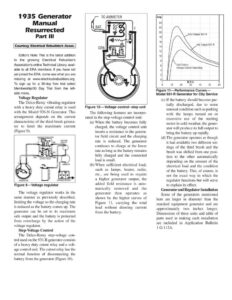
1935 Generator Manual Resurrected Part Ill Courtesy Electrical Rebuilders Assoc. Editors Note: This is the latest addition to the growing Electrical Rebuilder’s Association’s online Technical Library, avail- able to all ERA members. If you have not yet joined the ERA, come see what you are missing at www.electricalrebuilders.org. To sign up for a 30-day free trial select Membership/30 Day Trial from the left- side menu. Voltage Regulator The Delco-Remy vibrating regulator with a heavy duty cutout relay is used with the Model 936-N Generator. This arrangement depends on the current characteristic of the third-brush genera- tor to limit the maximum current (Figure 9). VOLTAGE REGULATOR IGNITION SWITCH IGNITION COIL ff GENERATOR Figure 9—Voltage regulator The voltage regulator works in the same manner as previously described, limiting the voltage so the charging rate is reduced as the battery comes up. The generator can be set to its maximum safe output and the battery is protected from overcharge by the action of the voltage regulator. Step-Voltage Control The Delco-Remy step-voltage con- trol used on the 931-R generator consists of a heavy duty cutout relay and a volt- age control unit. The cutout relay has the normal function of disconnecting the battery from the generator (Figure 10). TO AMMETER Figure 10— Voltage control—step unit The following features are incorpo- rated in the step-voltage control unit: (a) When the battery becomes fully charged, the voltage control unit inserts a resistance in the genera- tor field circuit and the charging rate is reduced. The generator continues to charge at the lower rate as long as the battery remains fully charged and the connected load is small. (b) When sufficient electrical load, such as lamps, heater, radio, etc., are being used to require a higher generator output, the added field resistance is auto- matically removed and_ the generator then operates as shown by the higher curves of Figure 11, carrying the total load without drawing current from the battery. old Output 931-R Cold Output Voltage Control Operating Figure 11—Performance Curves— Model 931-R Generator for City Service (c) If the battery should become par- tially discharged, due to some unusual condition such as parking with the lamps turned on or excessive use of the starting motor in cold weather, the gener- ator will produce its full output to bring the battery up rapidly. (d) The generator operates as though it had available two different set- tings of the third brush and the brush was shifted from one posi- tion to the other automatically depending on the amount of the electrical load and the condition of the battery. This, of course, is not the exact way in which the regulator functions but will serve to explain its effect. Generator and Regulator Installation Some of the generators mentioned here are larger in diameter than the standard equipment generator and are approximately two inches longer. Dimensions of these units and table of parts used in making each installation are included in Application Bulletin 1 G-112A.