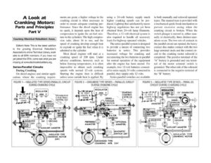
A Look at Cranking Motors: Parts and Principles Part V Courtesy Electrical Rebuilders Assoc. Editors Note: This is the latest addition to the growing Electrical Rebuilder’s Association’s online Technical Library, avail- able to all ERA members. If you have not yet joined the ERA, come see what you are missing at www.electricalrebuilders.org. Series-Parallel Circuits During Cranking On diesel engines and similar appli- cations where the cranking require- ments are great, a higher voltage in the cranking circuit is often necessary in order to ensure adequate cranking per- formance. Since the diesel engine has no spark, it depends upon the heat of compression to ignite the air-fuel mix- ture in the cylinders. The high compres- sion ratio, about 16 to one, and the speed of cranking develop enough heat to explode or ignite the fuel when it is admitted to the cylinder. Most diesel engines will start at a cranking speed of 200 rpm. Under adverse conditions, however, such as below freezing temperatures, it is often impossible to obtain such cranking speeds with normal 12-volt systems. Starting the engine then is difficult unless some outside heat is applied. By using a 24-volt battery supply much higher cranking speeds can be pro- duced. Lighting that satisfactorily meets highway regulations has not yet been obtained from 24-volt lamp filaments. Therefore, a 12-volt electrical system is also required to handle all accessory loads for highway operated vehicles. The series-parallel system is designed to provide a means of connecting two batteries in series. This provides increased voltage for cranking and reconnecting the two batteries in parallel for normal operation of the equipment after the engine has been started. For example, two 12-volt batteries connect- ed in series supply 24 volts; connected in parallel, they supply only 12 volts. Series-parallel switches are available in both manually and solenoid operated types. The manual type is provided with a mechanical quick-break mechanism to prevent excessive arcing when the cranking circuit is broken. When the switch plunger is moved in, either man- ually or electrically, three distinct oper- ations occur. The two sets of contacts in the parallel circuit are opened, the heavy contact disc makes contact with the two large terminal studs and the control cir- cuit to the cranking motor solenoid is completed. The positive terminal of the “A” battery is grounded and one termi- nal of the motor solenoid switch is grounded. The other side of the solenoid is connected to the negative terminal of the “B” battery. FIGURE 1—INSULATED TYPE SERIES-PARALLEL CIRCUIT DURING CRANKING CYCLE 12 VOLT STARTING 12 VOLT “SOLENOID al D . Sep CONTROL SERIES — 5 l SWITCH, 12V SERIES — INSULATED TYPE CRANKING MOTOR (24V) ff PREFERRED AMMETER FIGURE 2— GROUNDED TYPE SERIES— PARALLEL CIRCUIT DURING CRANKING CYCLE REGULATOR B ARM F mec PARALLEL + SS! AMMETER, | GROUNDED TYPE CRANKING MTR. 24V FIGURE 3—INSULATED TYPE SERIES— PARALLEL CIRCUIT DURING CHARGING CYCLE REGULATOR FA+ _GROUND mil AUXILIARY AMMETER INSULATED TYPE CRANKING MOTOR