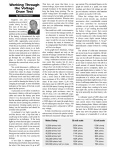
Working Through the Voltage Draw Test By Jack Henderson Suppose you are working on a car which cranks slowly for the first start of the day. You have determined that there is no cranking problem in the morning if the battery is disconnected the night before, which indicates that the battery itself is OK. Apparently, some circuit is remaining active and draining the battery while the car is parked, so the next task is to determine which circuit is at fault. This is a two-part process: You have to monitor some indication as to whether or not the current leak is present, while you go through the car pulling fuses and plugs to identify the component that interrupts the current leak when you dis- connect it. You could disconnect a different cir- cuit each evening to see if the battery would then retain its charge overnight. This is not an attractive prospect as trying a different circuit each day could easily take several weeks, and during that period you would be abusing the battery by dis- charging it each night. A more immediate indication of the status of the leak would speed up the process. A procedure not to follow would be to disconnect a battery cable and scrape the cable end across the battery post from which it was disconnected, in the hope that the resultant sparking would decrease when the circuit causing the problem is disconnected. Creating sparks next to a battery can be hazardous and should be avoided when possible. A mechanic’s test light, typically an awl-like device with a clip lead and a small lamp in the handle, could safely be employed as an indicator. If the lamp lights up when the test light is connected in series between a battery cable and the battery post from which it was removed, there is a significant current leak. Disconnect circuits one at a time until the lamp goes out, and the last circuit discon- nected is the one that was causing the leakage. A test light is adequate for trou- bleshooting most battery drain problems, but what if the lamp never lit up at all? That does not mean that there is no current leakage, it just means that there is enough resistance in the leakage path to keep the lamp from glowing. The so- called “voltage draw” test employs a volt- meter instead of a test light, and provides a more sensitive indication. Whereas a test light will simply be dark for all leakage currents below a certain value, the voltage draw test can differentiate leakage cur- rents down to zero. e¢ You could use a milli- or microamme- ter to measure the leakage current, or an ohmmeter to measure the resist- ance of the leaky circuit, but in either case it would be very easy to damage or destroy the meter. A voltmeter, set to a range greater than battery voltage, will be in no danger. As the graph below illustrates, voltage draw readings depend not only on the amount of leakage current but on the per- formance rating of the voltmeter as well. Using a voltmeter to measure a current may sound like voodoo, but it’s just a roundabout application of Ohm’s Law. A voltage draw test divides the battery volt- age in proportion to the known resistance of the meter and the unknown resistance of the leakage path. Set to the 20-volt scale, a meter rated at 5,000 ohms/volt has a resistance of 20 x 5,000 or 100,000 ohms. If the meter shows 12.56 volts, then there must be .0001256 amp (12.56 volt/100,000 ohms) flowing through the meter. If the battery voltage is 12.60, then the leakage path resistance must be 318.47 ohms (.04 volt/.0001256 amp). Leakage current is more meaningful than resistance, so for 12.56 volts measured on a 5,000 ohms/volt meter the graph shows the 40 milliamperes that flow when a 318 ohm leakage path is subjected to full bat- tery voltage. To find a troublesome current leak it is not necessary to know the precise correla- tion between measured voltage and leak- age current. The calculated figures on the graph are useful as a guide, but meter readings and ohms/volt ratings are sub- ject to tolerance variations and batteries are seldom at exactly 12.60 volts. When the voltage draw test was devised several decades ago, electrical accessories drew considerable current and were controlled by mechanical switches so test results were essentially go/no-go. A “go” reading, less than half the battery voltage, meant that current leakage was not significant. (Only rarely was the reading zero volts, because there is always some slight current leakage through electrical insulators.) A “no-go” reading was essentially battery voltage, and indicated a failed switch or a wiring short. The advent of solid-state electronics put an end to go/no-go simplicity. On late- model vehicles some solid-state circuitry may not shut off until 30 minutes or more after engine shutdown. And when the final at-rest state is reached, there will still be a small amount of current flowing to the alternator and to computers, alarm sys- tems, and digital clocks or radios. A “nor- mal” current drain could be several mil- l