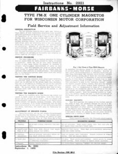
Instructions No. 2921 FAIRBANKS-MORSE TYPE FM-X ONE CYLINDER MAGNETOS FOR WISCONSIN MOTOR CORPORATION Field Service and Adjustment Information GENERAL DESCRIPTION The one cylinder magnetos whose parts are li Pages 2and4 of this instruction sheet were built sy cally for application on Wisconsin sing] ylinder engines. The variations of the Type FN-X1A7 mag o are all ofa special base mounting design witha shaft height o and the modifications of the Type FM-X1B7 special mounting flange. The masnetic and « cuits of all units are identical, with a two rotor and a single lobe cam producing = per revolution. Rotation of the base- hen viewed fromthe netos rotate le pawl im oviding an low engine spec Lings which facili sified and retarded ig- SERVICE PROCEDURE The table below gives a logical procedure to follow when an engine fails to start, ishard to start, or misses in operation. Since the use of this table locates the trouble in many cases before the magneto is reached, it prevents all-too-common maladjustment of parts in good condition. Type FM-X magnetos are built in sealed frames which should be opened only when it is certain that the ignition spark produced is unsatisfactory. This condition may be devermined by ignition spark tests which are easily made in the field. TESTING THE IGNITION SPARK With aproperly adjusted spark plugin good condition, the ignition spark should be strong enough to bridge a short gap in addition to the actual spark plug discharge. This may be determined by holding the end of the ignition cable not more than 1/16 in. away from the spark plug ter- minal. The engine should not misfire when this is done. Ignition tests made while any part of the system is wet are useless. TESTING THE MAGNETO SPARK Remove the ignition cable from the insert a short piece of stiff wire. id this wire to within 1/8 in. of the engine block. 1 th ne over slowly andwatch carefully for the spark wnich should occur at the instant the impulse coupling releases. Ifa strong spark is observed, it is highly recommended that the mag— neto be eli ated as the source of the difficulty and that the cable, terminals, and spark plug be thoroughly in- spected. cap socket and & ADJUSTMENT OF BREAKER POINTS Remove themagneto end cap and compare the arrangement of parts with the drawings of Fig. 1. The breaker points should then be inspected for evidence of pitting or pyra- miding. A small tungsten file or fine stone may be used TROUBLE POSSIBLE CAUSE SUGGESTED REMEDY A. Flooding C. Ignition Loose or corroded terminals; broken ca- connections |Jble; short circuited switch. D. Spark plug or carbonized insulator. Points, impulse coupling. Instructions No. 2921] September 1, 1950 Hot or cold engine; over-rich fuel mix |Dry out cylinde ture. let engine stan B, Insufficient [Hmpty fuel tank; clogged fuel supply |Replenish fuel supply. fuel or air line; clogged air intake. Clean air intake system. Cle 1 or replace cable terminals. joints. Test and replace cable. OLN 2 _- CONDENSER MEASURE BREAKER POINT GAP WHEN OPEN. ADJUST TO 0.015 INCH FULCRUM PIN SNAP RING BREAKER ARM BREAKER ARM TERMINAL c Fig. 1. End Views of Type FM-X Magneto to resurface the points, except in the case of badly worn or pitted points, which should be replaced. Removal of worn points may te accomplished by removing the fulcrum pin snap ring, thebreaker arm terminal screw, andthe contact support locking screws, all of which are identifiedin Fig. 1. If it is necessary to resurface or replace the breaker points, it will also be necessary to adjust them to their proper clearance, which is 0.015 in. at full separation. This adjustment is made in the following manner: Loosen the contact support locking screws, then move the contact support until the proper breaker point clearance is ob- tained. This is accomplished by means of a screwdriver inserted in the horizontal slot at the bottom of the con- tact support and pivoted between the two small bosses on the bearing support. Lock the assembly inplace by tight- ening the locking screws and make a final measurement of the breaker point gap after the locking screws are tight- ened. SEALING MAGNETO Type FM-X magnetos are sealed at the factory against the entry of dust and moisture through the use of a var— nish-coated gasket joint. Opening the magneto for breaker point adjustment or other service necessitates resealing of the magneto upon reassembly. The surfaces between the magneto frame andthe end cap shouldbe cleaned thoroughly, a new gasket should be provided, and the joint should be sealed with a coating of FMCO2 Gasket Sealing Varnish. SPECIAL DRIVE GEAR Flange mounting magnetos for Wisconsin motors require r. Crank engine slowly with fuel shut off; or d idle for a short time. Clean fuel system and check carburetor. Inspect soldered or clamped Corroded, worn or damaged points; cracked |New plug. Clean pointsandinsulator. Adjust points to recom- mended opening. Never attempt to adjust center electrode. See instructions be