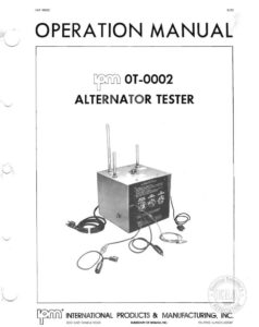
INF-353C 7/77 OPERATION MANUAL ream OT-0002 ALTERNATOR TESTER ; INTERNATIONAL PRODUCTS & MANUFACTURING, INC. 200 EAST DANIELS ROAD SUBSIDIARY OF WABASH, INC. PALATINE. ILLINOIS 60067 CHECK LIST Immediately after being unpacked, this equipment should be inspected for possible damages incurred during shipment. OT-—0002 ALTERNATOR TESTER QD) SOCKET (1 piece) UY 15/16″ <> <=) ADAPTER FOR CHRYSLER IPM WARRANTY OPERATION MANUAL. CoA ¥OT-0002 ALTERNATOR TESTER | OPERATION INSTRUCTIONS Lexi OT-0002 OPERATION INSTRUCTIONS GENERAL DESCRIPTION The OT-0002 ALTERNATOR TESTER permits you to make fast and accurate output checks on Chrysler, Ford and GM alternators (including GM integral alternators). It does not test brushless, 2-phase or self-excited types. {t’s easy to use. After hooking up the leads, depress two test buttons and observe the pane! lights for results. The actual test requires less than six seconds. A 12-volt de potential is applied across the green and yellow leads. The red lead serves as the pick-up for the sensing circuit. The speed of the drive motor, which will vary according to the alternator load, will not affect the tester’s accuracy. An automatic reset circuit breaker protects the critical circuits in the 01-0002. There is no shock hazard to the operator. OPERATION HOOK-UP COLOR-CODED INSTRUCTIONS for hook-up and mounting appear on the front panel. Once connections have been made, simultaneously depress the test buttons located on either side of the tester-and observe the green light located in the lower center of the panel. One of the following will occur: 1. Light stays on — alternator js good. 2. Light does not come on — alternator is bad. 3. Light comes on then goes out — alternator is bad. The small red panel light located at the top right will in- dicate the diode trio’s condition: 1. Red light stays off — trio is good. 2. Red light comes on — trio is bad. The OT-0002 operates on 120-volt ac. Remember: 1. Use the socket or adapter for driving the unit under test. 2. Refer to the appropriate instructions for hook-up Procedure. Wrong hook-ups will cause no damage. 3. When testing Chrysler and early Ford alternators, use the special adapter mounted on top of the tester. 4. Both test buttons must’ be depressed at the same time to activate drive motor and tester. 5. Use a pulley on the alternator to avoid the possibili- ty of damaging the brush assembly, FOR TESTING LATE-MODEL GM integra! alternators, connect green and red leads together as shown on the panel; however, use the black lead with special adapter this time, hooking it up as you normally would the green. For testing Motorola alternators, use the GM post. If the Motorola alternator has an integral diode trio, plug the tester’s black lead into the male plug bolted to the in- sulated post on the alternator. Test the same way as for GM integral alternators. When testing double-insulated brush alternators (e.g., late Chrysler), make these connections: Clip the yellow lead to alternator housing; run a jumper from this clip to one field terminal; connect green lead to the other field ter- minal; connect red lead to the positive (B+) post. TESTER CHECKS & ADJUSTMENTS THE TESTER SHOULD BE PLUGGED into a live 120- volt ac circuit. If it is and if the motor and test light fail to work, the circuit breaker inside the unit is probably bad. In the green lead there is an AGC 4-amp fast-blow fuse. It protects the tester in case the green lead becomes grounded. CAUTION: Any time a unit with a shorted rotor is tested or the buttons are pushed with the green lead grounded, there is a good probability of blowing the green lead fuse. Replacement of the fuse should be made with an AGC 4-amp only. A larger fuse could cause damage to the logic circuit or power supply and will VOID any warranty. To test the green light on the front panel, hook red and green leads together. Push both test buttons; the motor should start and the green light should come on. Failure of the light to come on indicates a bad bulb or bad fuse. A type 1889 bulb and an AGC 4-amp fuse are used. To test the diode trio indicator bulb, run a good alter- nator of a non-integrated type such as Chrysler or Ford on the unit. If the light is good, it should come on. (Do not attempt to replace this light without special instructions. It is a light-emitting diode that must be soldered in. It can not be replaced from the front panel.) THE SENSITIVITY of your tester may need adjusting oc- casionally, due to vibrations that alter the setting of the potentiometer on the logic circuit board. Make the adjust- ments this way: - Remove plug from rear of case. 2. Connect red lead and green lead test clips together. 3. With both test buttons depressed, turn potentiometer slot CW or CCW. until green panel light just comes on. (With older models, which have a single-turn potenti- ometer, this setting is relatively critical; newer models, sing have a 20-turn control allowing more toler- ance. Potentiometer on Logic Circuit; . Board —~14 Hole through Which Potentiometer Can Be Reached Sensitivity adjustments: on the tester can be trode by. resetting the potentiometer on this circuit’ boatd, acces- sible through the rear of the case. MAINTENANCE Properly maintained and operated, the 01-0002 Alter- nator Tester will give you trouble-free service fat many. years. When parts are needed, they can be readily ob- tained from IPM.