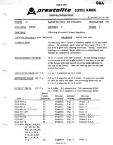
GGA FILE IN THE eS, Prestolite sixick Maal GENERATOR SECTION (Issued 3~16-78) _ VOLTS = 12 ROTATION CWDE CONTROL GROUND POLARITY See Tabulation LUBRICATION BRUSH SPRING TENSION FIELD COIL DRAW (70°F.) MOTORING DRAW (70°F.) RATED OUTPUT See Tabulation VENTILATED Yes BRUSHES 2 POLES 2 Vibrating Current-Voltage Regulator BEARINGS _ Ball at both ends Periodically add 5 drops of medium engine oil to end head oilers. At overhaul, pack open ball bearings 1/4 to 1/2 full with a good ball bearing lubricant. NOTE – some ball | bearings are sealed, these units are prelubricated and require no additional lubrication. 34 to 41 ounces with new brushes. Brush spring tension is measured with the scale hooked in the hole in the end of the brush arm and pulled on a line perpendicular to the top of the brush. Take the reading just as the arm leaves the brush. 1.1 to 1.3 amperes at 10.0 volts 2.3 to 2.6 amperes at 10.0 volts. If generator has felt oil seal in drive end head, the motoring draw will be 3.1 to 3.5 amperes at 10.0 volts. OUTPUT TESTS (70°F.) 14,6 volts, 4.0 amperes at 900 maximum RPM. 15.0 volts, 40.0 amperes at 1500 maximum RPM. Rated Output Ground Internal Special Unit Amperes Polari Wirin Instructions GGA-4801A Negative Fig. 1 Notes 1, 2 GGA-4812A Positive Fig. 2 Note 3 GGA-4813 40 Positive Fig. 2 Note 3 GGA-4814A,B,F,G,H Positive Fig. 2 Note 3 GGA-4814EN Negative Fig. 2 Note 3 GGA-4816 35 Positive Fig. 2 Notes 2,3,4 GGA-4816T .35 Positive Fig. 2 Notes 2,3,4,5 GGA-4817 Positive Fig. 2 Notes 2,3,4 GGA-4817T Positive Fig. 2 Notes 2,3,4,5 GGA-6001 AB, AC, AD, AE, AF, AH, AJ, AL, AM, AP, AR, AV, EN,K,L,M,N, N-81, P, R, SN SN-1,V,W, X, Y,Z Negative Fig. 2 Note 3 Printed in U.S.A. GGA~-6001, A, AK, B, c,D,E,F, G,H,J,N-1, 5, 5-1 40 Positive Fig. 2 Note 3 GGA-6002, A, AA, B, BA, C, D, ’ »G, S$, S-l 40 Negative Fig. 2 Note 3 GGA-6003, A, B, C,D,E, F,G,5-1 40 Negative Fig, 2 Note 3 GGA-6004, A, B, S-1 40 Negative Fig. 2 Note 3 GGA-6006, A, B, C, D,E, F,G,H, J, K, L, N, P, R,S, VW 40 Negative Fig. 2 Note 3 GGA-6009Y 40 Negative Fig. 2 Note 3 NOTE 1 – Connect field terminal to armature terminal when measuring motoring draw. NOTE 2 – Stake drive end bearing screws. NOTE 3 – Connect field terminal to ground when measuring motoring draw. NOTE 4 – This generator has a felt oil seal in the drive end head which will affect motoring specifications as noted. NOTE 5 – After inspection of the various parts, paint terminal stud and brush holder insulation with red glyptol. Cover glyptol and all metal surfaces except pilots, head seats, threads, commutator and bearing surfaces with air-drying, fungus-resistant varnish. Allow varnish to soak into field coils and armature windings. Drain and dry thoroughly before assembling generator. FIELD GROUND INSULATED BRUSH GROUNDED BAUSH VIEWED FROM COMMUTATOR END INSULATED BAUSH’ GROUNDED BAUSH VIEWED FROM COMMUTATOR ENO Figure 1 Figure 2 Printed in U.S.A.