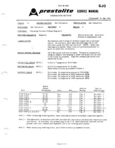
FILE IN THE GJO S, Prestosite seRick MANUAL GENERATOR SECTION (Issued 3-16-78) VOLTS t2 RATED OUTPUT See Tabulation VENTILATED See Tabulation ROTATION See Tabulation BRUSHES 2 POLES 2 CONTROL Vibrating Current-Voltage Regulator GROUND POLARIT Negative BEARINGS Ball at drive end. Absorbent bronze at commutator end. LUBRICATION Periodically add 5 drops of medium engine oil to end head oilers. At overhaul, pack open ball bearings 1/4 to 1/2 full with a good bali bearing lubricant. NOTE – Some ball bearlngs are sealed, these units are prelubricated and re- 7. guire no additional lubrteation. BRUSH SPRING TENSION 18 to 36 ounces with new brushes. Tension is measured by using an adaptor and hooking it under the brush arm as near to the brush as possible. Take the reading just as the arm leaves the brush. . FIELD COIL DRAW (70°F. } 1,6to 1,7 amperes at 10.0 volts MOTORING DRAW (T0°F.) 2.9 to 3.3 amperes at 10.0 volts (Have field terminal grounded to frame, )} OUTPUT TESTS (70°F. ) 15.0 volts, 13 amperes minimum at 1750 RPM. 15.0 volts, 25 amperes at 2300 maximum RPM. 15.0 volts, 30 amperes at 2700 maximum RPM. 15,0 volts, 12 amperes at 1900 maximum RPM. Rated Output Internal Special Unit (Amperes) Vent. Rot. Wiring Instructions GJO-T101A4,S 25-30 Yes cw Fig. J See Note |! GJO-7102S8 25-30 Yes CW Fig. I See Note 1 GJO-7104A 29-30 Yes CW Fig, 1 pee Note 1 GJO-TLOSA : 25-30 Yes CW Fig. 1 See Note 1 GJO-T1O6A, B 29-30 Yes CW Fig. 1 See Note 1 GJO-73015 12 No cw Fig. 1 See Note] GJIO-F3998 12 Ne cc Fig. See Note] GJIQO-7402A,5 29-30 Yes CW Fig. 2 See Notes 2,3 GJO-T403A 29-30 Yes cw Fig. 2 See Note 3 GJO-7501A, C, D, §, S-1 12 No CW Fig. 2 See Note 3 Note 1 – When measuring motoring draw, have field and armature terminals connected together. Note 2 – This generator is manufactured with extended life lubrication and does not require periodic lubrication. At overhaul, the grease plug in the C, E, head should be removed and the grease reservoir cleaned and repacked with a low melting point grease. Note 3 – When measuring motoring draw, have field terminal grounded to frame. Printed ip USA {GJO Continued} FicLo TERMINAL AAMATURE TERMINAL GROUNDED INSULATED BRUSH ‘ BRUSH EWED FROM COMMUTATOR END Figure ] Printed in U.S.A. SQ Prestolite SENICE MANUAL TERMINAL GROUNDED BRUSH INSULATED BRUSH VIEWED FRO COMMUTATOR END Figure 2 —