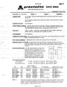
” “TRANSMISSION ” See ‘Tabulation. : SWITCH. ACTION ‘TEST.< ‘To test switch. action on ‘elutelr type’ TEST SP ECIFICA TIONS | ©, prestolite SERVICE MANUAL STARTING MOTOR SECTION Issued 3-16-78 ROTATION, See Tabulation | NOLS” Bo POLES 4 on BRUSHES 4 LUBRICATION” _ oo At overhaul, all bronze ‘bearings should be well lubricated with medium : engine oil. . . —— -Cover armature shaft at Drive End with a film of. lubricant before : assem - bling drive. : - STARTING SWITCH See Tabulation. BRUSH SPRING TENSION 42 to 53 ounces with: new brushes. Measure with scale hooked under. . yo ‘the brush spring néar ‘the'brush. Pull on a Line parallel to'the face of the -. brush and take the reading just as the spring leaves. the brush. END PLAY. —_._—s_s 005”” to. 930°?.: “Adjust by. installing MI- -54. (/32"* thick) or MU-~S4B (3/64" thick) on commutator end of shaft as 5 needed. oa COMMUTATOR | END ) HEAD Be sure- telt: oiling’ ‘pad ts" in the outer end ot: ‘thé comuvutator erid head ad " before-assembling. head. on the motor: POLE SHOE: ASSEMALY Install pole shoes ‘60 o that the long tip: ‘is: the. trailing edee.. "MAGNETIC SHIFT CLUTCHES in operating the Solenoid’ plunger’ by’ ‘hand, it will: be noted that - first, the switch contact-is made. and then, about 3/1 6”’ further, travel bot~- - toms the plunger and brings its outer end about fiush with. the solenoid... es housing. “fea motors, slip a steei spacer, (See il- : Justration for the dimensions) over the armature shaft bétween the pinion and ° the thrustwasher next to the outer “pinion housing bearing, “With this”: * spacer in place, the magnetic switch - «should bottom and the switch contact betel or he . should close, ‘under: normal voltages.’ No Load Draw 10 volts, 35 maximum amperes, 4800 minimum RPM. Stall Torque 4 volis, 175 maximum amperes, 6.5 minimum Lbs. Ft. No Laad (Oi! Seal) 10 volts, 48 maximum amperes, 3400 minimum RPM. Starting Switch ; - cote Unit Rot. Type Mounted Transmission Special Instructions MC T-6101 CW Solenoid On Motor Mag. Shift Ciutch See Note 1 MCT-6103 CW Solenoid On Motor Mag. Shift Clutch See Note 2 MCT-6105M CW Separate Bendix See Notes 3,4,5 MCT-6106M CCW Separate Bendix See Notes 3,4,5 MCT-6110 cw Solenoid On Motor Mag. Shift Clutch See Note 2 MCT-6202M CCW Sclencid | On Motor Bendix See Notes 4,6 MCT-6203M cw Solenoid On Motor Bendix See Notes 4,6 MCT-6301 cw Solenoid On Motor Mag. Shift Clutch See Note 2 NOTE 1 - - With switch closed and plunger fully bottomed, a clearance of 3/32’'+1/32’’-1/64’’ should be maintained between the outer edge of the pinion and the drive end thrust - washer. Have armature pushed toward commutator end and adjust by screwing switch plunger or link screw in or out. Printed in U.S.A. & prestolite ‘SERVICE MANUAL MCT continued NOTE 2 - -. oa... ... Should be maintained between the outer -edgé of the pinion and thé pinidn stop. “Have ~ armature pushed toward commutator end and adjust by screwing switch plunger or’ link screw in or out. oo - Use MN-18 of MN-18E thriistwashers as required to hold dimension of 1. 220°’ to 1.348” including end play with drive retracted measured from mounting flange to outer edge of pinion or 1.967" to 2.095*’ including end play with drive extended. “NOTE 3 - After installation of new field coils, paint the inside of the frame and soak the field coils with air-drying varnish. Keep varnish off of brush leads, -pllot seats and heads.. ” When reusing the old armature, its core and windings should be given the same , ‘treatment, being careful to keep the commutator and bearing surfaces clean. NOTE 4 - NOTE 5 - a Pack gear cavity with 1,2 to 2,.0 ounces of medium grease.” Use MU-54F, MU-54J or MU-54N thrustwashers..as. required {o hold dimension:of 4, 220” to 1.342’" including end play with drive retracted measured from mounting _, flange to outer edge of pinion or 1.967’' ta 2.089’ including end play with drive ex- | aS tended ee ee NOTE. 6.-— , -POST. INSULATED _ INSULATED BRUSH BRUSH INSULATED INSULATED . GROUNEE > ~ BRUSH Sete . VIEWOD FROM COMAMUTATOR OD 2 iE Flle TOMMUTATOR END With switch closed and the plunger fully-bottomed, a clearance of 3/32’+1/32”?-1/64″” ~- Internal Wiring of CWDE Type Motors Internal Wiring of- CCWDE Type Motors Printed in LLS.A.