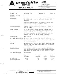
©, prestolite_? ____ Starting Motors SERVICE mage Lot 2 INFORMATION Issued 3/16/78 VOLTAGE 24 ROTATION CWDE BRUSHES 4 POLES 4 DIAMETER 4-1/2″ LUBRICATION Soak absorbent bronze bearings and felt oiling pads in SAE 20 oil. Allow to drain thoroughly before assembly. Lubricate armature shaft and splines with low tem- perature grease before assembling drive. BRUSH REPLACEMENT Replace brushes when they have worn to a length of 1/4″ or less. SPRING TENSION 32 to 40 ounces with new brushes. Measure with a spring scale hooked under the brush spring at the brush. Pull the scale on a line opposite the line of force exerted by the brush spring and take the reading just as the spring leaves the brush. TRANSMISSION Mag. Clutch POLE SHOE INSTALLATION If field coils are replaced, install pole shoes so that the short edge is pointing in the same direction as armature rotation. END PLAY Adjust to .005″ to .030″ with thrust washers at com- mutator end. See Parts & Equipment List for thrust washer package. SHIFT ADJUSTMENT With plunger sealed and pinion pushed toward comm. end, adjust link screw so that the clearance between the pinion and pinion stop is 3/32″ + 1/32″ – 1/64″. TEST SPECIFICATIONS (77°F /25°C) Terminal Maximum Torque Voltage Amperes RPM Ft. Lbs. No Load Test 20.0 38 6,500 -O- Stall Torque Test 6.0 175 – 0 – 7.0 File in the STARTING MOTOR SECTION Printed in USA. 1-600 SERVICE MANUAL [ sp ©, prestolite. Starting Motors Page 2 of 2 SERVICE Issued 3/16/78 INFORMATION a Unit *Pinion Position Special Notes MHP-7101T 1-9/32″ – 1-27/64″ Note 1 * Pinion position “at rest” measured from mounting flange to outer edge of pinion. Note 1 – After inspection of various parts, paint terminal stud and brush holder insulation with red glyptol. Cover glyptol and all metal surfaces except pilots, head seats, commutator and bearing sur- faces with an air-drying, fungus-resistant insulating varnish. Allow varnish to soak into field coils and armature windings. Drain and dry thoroughly before assembling the motor. TERMINAL TAB VIEWED FROM COMMUTATOR END reii Ct & IN restolte. MHP Pump Motors SERVICE Page 1 of 2 INFORMATION Revised 4/1/88 VOLTAGE 24 ROTATION See Tabulation BRUSHES 4 POLES 4 VENTILATED No 4-1/2″ BEARINGS LUBRICATION BRUSH REPLACEMENT SPRING TENSION POLE SHOE INSTALLATION END PLAY TEST SPECIFICATIONS No Load Test Stall Torque Test UNIT MHP-4001,5 MHP-4002 ,S CWDE CWDE MHP-40065S MHP-4007 ,A CWDE CCWDE File in the 1.400 SERVICE MANUAL ROTATION D.E. BEARING FRAME DIAMETER Absorbent bronze bearing used at commutator end. See tabulations for type of drive end bearing. Soak absorbent bronze bearings and felt oiling pad with SAE 20 oil. Allow excess oi] to drain out before assembling end head on motor. Ball bearings, when supplied for drive end, are pre- lubricated and sealed. No additional lubrication is required. The brushes must be replaced when they have worn to a length of – See tabulation, 32 to 40 ounces with new brushes. Measure with a spring scale hooked under the brush spring at the brush. Pull the scale on a line opposite the line of force exerted by the brush spring and take the reading just as the spring leaves the brush. When replacing field coils, install the pole shoes so that the long edge is pointing ‘in the same direction as the armature rotation. Adjust to .005″ minimum with thrust washers at C.E. bearing. Refer to Parts & Equipment List for thrust washer package. (77°F /25°C)) Terminal Max imum Torque Voltage Amperes RPM Ft. Lbs. 22 40 7000 Min. 0 8 230 0 10.5 INTERNAL BRUSH WIRING _ REPLACEMENT Sealed Bal] Fig. Sealed Ball fig. Replace at 5/16″ or less Replace at 5/16″ or less — Fidq. Sealed Ball Fig. Replace at 5/16″ or less Replace at 1/4″ or tess 1 1 MHP-4003 ,A CCWDE Sealed Ball 2 Replace at 1/4″ or less MHP-4005 CCWDE Sealed Ball a 3 Replace at 5/16″ or Tess ] 2 => PUMP MOTOR SECTION