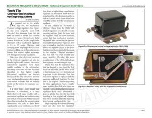
ELECTRICAL REBUILDER’S ASSOCIATION—Technical Document CS201503D Tech Tip Chrysler mechanical voltage regulators BY BOB THOMAS A pointed out in the article on page five, the mechanical B-circuit voltage regulators (see Figure 1) that were originally used with Chrysler’s first alternator from 1961 to 1969 are unable to handle field-current loads over 3 amps. Normal rotor field- current draw for a Chrysler single-field alternator with a mechanical regulator is 2.3 to 2.7 amps. Checking and verifying rotor amperage draw is vital when rebuilding one of these alternators. Rotors that require higher amperage will damage mechanical regulators. Note also, that electronic versions of the B-circuit regulator are able to handle higher field current. Electronic replacement regulators have been readily available in the aftermarket for many years now and can be easily identified by their lighter weight. Mechanical regulators are heavier, because of the relay which has an iron core. Mechanical regulators also require wire-wound resistors that are usually visible on the bottom the regulator (see Figure 2). If a rotor from a later model year alternator is substituted, it is very likely that it will cause trouble with a mechanical regulator, and problems may not surface immediately. While many of those later rotors had the same physical dimensions, the coils in them have significantly lower resistance, and their field draw is higher than a mechanical regulator can withstand. Field draw on some later Chrysler alternators can be as high as 7 amps, nearly three times what would be normal draw for a mechanical regulator. If you happen to encounter a Chrysler vehicle from the 1960s with a failed regulator, you should carefully examine and test both the rotor and the regulator. With the cover removed, notice that this mechanical regulator has a small wire connecting the ignition terminal to the relay (see Figure 3). That wire is actually a fuse link. It is there to protect the ignition circuit in the event that the rotor shorts internally to ground. In the original Chrysler regulators, this fuse link was even smaller and more sensitive. Chrysler, like most manufacturers of the 1960s, did not run their ignition circuit through a fuse. If you find that the regulator’s fuse link has burned in two, then the field draw was excessive, or the rotor, brush or field terminal were very likely shorted to ground in the alternator. That fuse link can be repaired or replaced with the same size and length fuse link. The fuse link in the original Chrysler regulators, for these applications, had a smaller more sensitive fuse link wire than our example. Some aftermarket mechanical regulators have since substituted a glass or plastic fuse for the fuse link. Installing a fuse in place of a burned fuse link is another option for repairing a mechanical regulator of this type. High amperage draw from the wrong rotor can also burn the regulator’s Figure 2—Resistors verify that this regulator is mechanical. An ERA Publication. ©2015, Electrical Rebuilder’s Association. All rights reserved. No portion of the guide may be reproduced in any way, or stored in any electronic retrieval system without the prior written consent of the Electrical Rebuilder’s Association. www.electricalrebuilders.org ELECTRICAL REBUILDER’S ASSOCIATION—Technical Document CS201503D www.electricalrebuilders.org upper contact set or even cause the contacts to fuse together and stick. This can cause either a no-charge if open or overcharging if stuck closed (see Figure 4). It is worth mentioning that most of these vehicles were equipped with ammeters built into the instrument cluster. All current flow into or out of the battery, with the exception of that required to crank the engine, has to pass through the ammeter circuit. The wiring harnesses of these vehicles were also assembled from sub harnesses. The engine harness is connected to the inside harness by way of spade connections on each side of the firewall. All alternator current must pass through a single spade connection at the firewall and then on to one side of the ammeter. Also connected to that same side is a distribution wire, which feeds the electrical loads of the vehicle, including ignition, lighting, and other accessories. The other side of the ammeter is connected to a wire leading back to another spade connection at the firewall and then on to a fuse link and the battery. With very few exceptions, this wiring harness was designed to handle no more amperage than the original alternator could produce. Even then, it was being pushed to the limit. The most common problem areas on this charging system are the spade connections at the firewall, both going into the ammeter and coming back out to the battery. Voltage will drop at the firewall in both directions. Deterioration of these connections is inevitable over time. When combined with prolonged high amperage, as in recharging a low battery, the terminals will lose their tension and exacerbate the problem. Repair options are: replacing the entire wiring harness or bypassing the firewall connections for both of these 10-gauge wires. The other problem you may encounter is resistance at the back of the ammeter, where its two studs are bolted through a plastic instrument cluster housing. If excessive amounts of current flow through these connections, the ammeter and studs can heat up and melt the plastic through which they mount, allowing the fastening nuts to loosen. The resulting condition, if not corrected, can destroy the plastic housing and the ammeter. While it is difficult to see these connections because of their location, they can be reached and felt by hand to check for tightness when servicing a vintage Chrysler vehicle with an ammeter. Doing this “feel” test with the engine running while loading the battery will allow you to feel for heat at the same time. If there is excessive resistance at the ammeter studs, you will be able to feel them warm up quickly. Figure 4—Upper contacts can stick if the wrong rotor is used. An ERA Publication. ©2015, Electrical Rebuilder’s Association. All rights reserved. No portion of the guide may be reproduced Page 2 in any way, or stored in any electronic retrieval system without the prior written consent of the Electrical Rebuilder’s Association.