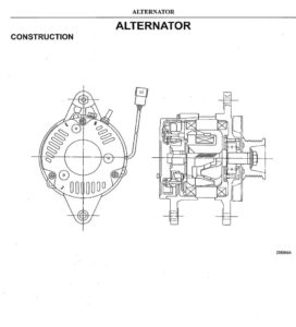
ALTERNATOR ALTERNATOR CONSTRUCTION ZEEQ63A WIRING DIAGRAM AvTay 4OO1d YALYVLS dOIWYANAS 0.85B/W SSANUYVH SISSVHO a0 O.5R/W 0.5R/W 0.85Y/8 BE 0.857/8 SSANUYVH NIVA ——o——— 74580 R, R, O.5R/W 0.85Y/B – uw mu | 4g0IG eas VM SSYVHD | Lo 4 431819 43aL4aN J | I ! | | } I CHARGING SYSTEM |e ALIVG NOUS > St-A =A9018 ASNS a LYVLS 49 NO HOLIMS NOILINSI ZEL814B EL-13-5 vator test, make sure that the battery is fully charged. A 30-volt voltmeter and suitable test probes are necessary for the test. When any fault is ¢ from the vehicle and disassemble, inspect and correct or reptace the faulty parts. Disconnect connector (IG, L) and ground vehicle side L terminal (small wire). come on 2? OFF Burned-out bulb Replace CHARGE warning lighl bulb? . = —<= Connect connector (iG, L) and * ground F terminal. ~ Terminal (Small wire) ZEEO64A fe) Does CHARGE warning light come on? N Faulty [C-regulator eee F a ee hos Faulty rotor or diode Loose drive belt or Faulty alternator parts except (C-regulator come on? Oulput Terminal nal voltage rpm. Less than 0.5 volt Altemator is in good condition More than Q.5 volt Faulty negalive diode ra eal ~~ Faully (C-requlator Does CHARGE warning light ONT Faulty diode assembly __ come on? OFF : — | Alternalor is in good condition | Measure the vollage across output and L. terminals wilh engine idling. Operate headiigh! high bearns with engine idling Less than 14.6 volts ONILOOHSATENOYAL dYwNGsaDOUd LSAL WALSAS ONISYVHOD YUOLVNAALTV ALTERNATOR DISASSEMBLY ; X : 127 - 157 NO j {13 - 16, 94 - 116) CL : Nem {kgf-m, ft-lbf} C ZEEQ65A {.Cover 7.Ball bearing - 13.Coil assembly * 2.Front cover 8.Plate 14.Heat sink * 3.Pulley assembly 9.Dust seal 15.Heat sink 4.Collar 10.Cover 16.Housing 5.Dust seal 11.Rotor assembly 17.Regulator 6.Plate 12.Stator assembly 13.Coil assembly Marks “ * “and “ + ” indicate that the key points of operation are explained in the text. NOTE aR snk mn DnB mn mak men en nat Ie elinntn 4h 0 AAR AAR A san badae mn mene nn T ALTERNATOR Key point of disassembly 2.Front cover To separate the front cove, insert a screwdriver into the clearance between the front cover and stator core. NOTE *Be careful not to damage the stator coil with the screw- driver tip. 3.Pulley assembly When separating the pulley assembly, secure the rotor periphery with a vise. Then, remove the pulley nut, pulley assembly and spacer. If the. pulley assembly is difficult to remove, use a general- purpose puller. . INSPECTION 1. Inspect the pulley for wear, cracks or damage. If faulty, replace. 2. Inspect each terminal for corrosion or damage. If faulty, repair or replace. STATOR COIL Stator coil resistance Measure resistance between the two stator coil leads. Unit: Q Maintenance standard | Service limit Remarks 0.036 - 0.039 Between the neutral point [20°C (68°F)] (N) and each lead wire If continuity does not exist between the leads, the stator coil circuit may be broken. Replace with a new stator coil assembly. Stator coil insulation resistance ( AAA ALTERNATOR ENERGIZING COIL Energizing coil Measure resistance between energizing coil leads. = , Unit: Maintenarice standard — Service limit 2.2 - 2.4 [20°C (68°F)] Energizing coil insulation resistance | Measure insulation resistance between the energizing coil and the core. . Unit:MQ Maintenance standard Service limit 5, min. 0.5 If insulation resistance is less than 0.5 MQ, replace with a new energizing coil assembly. ROTOR Rotor shaft outside diameter 1.Measure the outside diameter of the rotor shaft at the front bearing. , Unit: mm (in) Service limit 24,98 (0.9835) Maintenance standard ~ 25.00 (0.9843) EEE3-036 2.Measure the outside diameter of the rotor shaft at the vacuum pump. : Unit: mm (in) Maintenance standard Service limit 17.00 (0.6693) 16.98 (0.6685) ALTERNATOR ) HEAT SINK (DIODE) Heat sink (diode) continuity Attach one test lead of a circuit tester to the heat sink plate and the other to one diode terminal to check if continuity exists. With one test lead remaining attached to the heat sink plate, shift the other test lead to the other diode terminal to check if continuity does not exist. Similarly, conduct the above tests on the other two diodes. Continuity must exist in one direction only. If it exists in both directions, replace that diode. PERFORMANCE TESTS *Before conducting performance tests on the alternator Measuring regulating voltage | 1.Turn off SW» and turn on SW. 2.Measure the voltage by raising the generator speed up to the rated speed of 5,000 rpm. Unit: V Service limit Maintenance standard 14.0 - 14.6 Measuring alternator speed at 13.5 volts 1.Turn on SW, and SWp, and raise the generator speed gradually. 2.Turn off SW, if the voltage raises above that when the generator is stopped. 3.While observing the voltmeter, further raise the generator speed. 4.Check the generator speed when the voltmeter indicates 13.5 V. Unit: rpm Maintenance standard Service limit ‘900, max. EEE3-037E