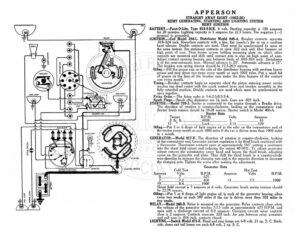
HORN BUTTON E }[-® 5 | DISTRIBUTOR ; wat ©) DasHLaMp = / / x \ OY yt a Ds CAegD 1 l | : \ . it Sy “NN S t, af SWITCH > re AMMETER S) STARTING SWITCH DIMMER RESISTANCE APPERSON STRAIGHT AWAY EIGHT (1925-26) REMY GENERATING, STARTING AND LIGHTING SYSTEM REMY IGNITION BATTERY.—Prest-O-Lite, Type 613-S.H.K. 6 volt. Starting capacity is 130 amperes for 20 minutes. Lighting capacity is 5 amperes for 22.5 hours. The negative (—) terminal is grounded. IGNITION.—Coil Model 284-L. Distributor Model 648-A. Breaker contacts separate .018-.024 inch. Resurface contacts with a fine, flat jeweler’s file or on a medium hard oilstone. Double contacts are used. They must be synchronized to open at the same instant. Set stationary contacts to open .022 inch with fiber bumper on high point of cam. Then loosen screws holding mounting plate on which other contacts are mounted and shift until contact arm is also on high point of cam. Adjust contact opening keeping gap between limits of .018-.024 inch. Distributor is of the semi-automatic type. Manual advance is 20°. Automatic advance is 15°. he breaker arm spring tension should be 17.5-20.5 ounces. ; Oiling.—Fill the grease cup on the side of the distributor housing with medium heavy grease and turn down two turns every month or each 1000 miles. Put a small bit of grease on the face of the breaker cam under the fiber bumper of the contact arm every month. Timing.—Breaker contacts begin to separate when the piston entering power stroke reaches top dead center with the spark control lever and breaker assembly in the fully retarded position. Double contacts are used which must be synchronized to open together. Firing Order.—The firing order is 1-6-2-5-8-3-7-4. Spark Plugs—Spark plug diameters are 7 inch. Gaps are .025 inch. STARTER.—Model 720-J. Starter is connected to the engine through a Bendix drive. he direction of rotation is counter-clockwise, looking at the commutator end. Starter brush tension should be Nie pune Starter switch is Model 406-A. tarter Data Torque R.P.M. Volts Amperes 0 Ib. ft. 6000.0 eee 5 eccesesseesecaceeeee 65 a a el ee Lock………….—–+« BAD ee cceeeceeeeeeeeee 570 Oiling —Put 5 or 6 drops of light engine oil in the oiler on the commutator end of the starter every month or each 1000 miles if the car is driven more than 1000 miles in a month. GENERATOR.—Model 917-V. The direction of rotation is counter-clockwise, looking at the commutator end. Generator current regulation is by third brush combined with a thermostat. Thermostat contacts open at approximately 165° cutting a resistance into the shunt field circuit and reducing the output 40-50%. To adjust generator output remove the commutator cover band and loosen the third brush adjusting screw on the generator end plate. Then shift the third brush in a counter-clock- wise direction to increase the charging rate and in the opposite direction to decrease the charging rate. Tighten the screw after making the adjustment. Generator Data Cold Test Hot Test Amperes Volts R.P.M. Amperes Volts R.P.M. 0 Y ee eeeeonrre 675 ~ see eee TD scecrosiesssexssreee 1900 Shunt field current is 5 amperes at 6 volts. Generator brush spring tension should he 22-28 ounces. Oiling:—Put 5 or 6 drops of light engine oil in each of the generator bearing oilers every two weeks or each 500 miles if the car is driven more than 500 miles in two weeks. RELAY.—Model 265-B. Relay is mounted on the generator. Relay contacts close when the voltage of the generator reaches 7-7.5 volts at approximately 675 R.P.M. and open with a discharge current of 0-3 amperes. Charging current when contacts close is 2 amperes. Contacts separate .020 inch. Air gap between relay armature and coil core is .016 inch, contacts closed. LIGHTING.—Switch Model 471-E. Head and stop lamps ane 6-8 volt, 21 ep. S. C. Dash, side, dome and tail lamps are each 6-8 volt, 2 cp. S