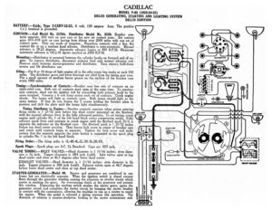
CADILLAC MODEL V-63 (1923-24-25) DELCO GENERATING, STARTING AND LIGHTING SYSTEM DELCO IGNITION BATTERY :—Exide, Type 3-LXRV-15-2G. 6 volt, 130 ampere hour. The positive L@/ (>) (+-) terminal is grounde IGNITION:—Coil Model No. 2179A. Distributor Model No. 5239. Breaker con- tacts separate .020 inch on new cars or for new set contact arms. Set contact gaps .015-.018 inch on cars having been driven over 2000 miles with one set of contact arms, They are made of tungsten. Resurface contacts with a fine, flat contact file or on a medium hard oilstone. Distributor is semi-automatic, Manual advance is 18-22 degrees. Automatic advance begins at 800 R.P.M. Maximum © O @ automatic advance is 1614-18 dgrees reached at 2000 R.P.M. 8 Mounting :—Distributor is mounted between the cylinder banks on forward end of en- é DISTRIBUTOR ine. To remove distributor, disconnect primary lead and manual advance rod. 5 = BREAKER emove shaft between starter-generator and distributor. Then remove hold-down O SE screws and lift distributor out. wart CONDENSER ‘ye a Oiling.—Put 8 or 10 drops of light engine oil in the oiler every two weeks or each 500 miles. The distributor gears and lower bearings are oiled from the timing gear case. Put a small amount of medium heavy grease on the surface of the breaker cam every 1000 miles. oe »_-” Timing :—Synchronization of Contacts:—Breaker uses two sets of contacts on an eight-sided cam. Both sets of contacts must open at the same time. To synchro- nize contacts, short out the ignition coil by connecting both primary leads to the same terminal. Connect a 6 volt lamp across each set of contacts. Crank engine slowly. The lamps will light as contacts open. Both lamps should light at the same instant. If they do not, loosen the 3 screws holding the breaker plate in position and shift the plate until the lamps light simultaneously. Timing Distributor to Engine:—Breaker contacts separate when piston entering firing stroke is 1 21/32 inch before top dead center measured on the flywheel, with the manual advance lever in the fully advanced position. To set timing, crank engine until cylinder No. | of the left hand block enters compression stroke. Fully advance spark lever and continue to crank engine until the flywheel mark IG/A is opposite the indicator on the flywheel case. The flywheel mark is 1 21/32 inches before top dead center position. Then loosen Jock screw in center of breaker cam and rotate until contacts begin to separate. Tighten the lock screw and make certain that the segment opposite the rotor button is connected to the spark plug in cylinder No. | inthe left hand block, i ge NY Firing Order:—The firing order is 1L-4R-4L-2L-3R-3L-2R-IR. Spark Plugs:—Spark plugs are A.C. 7% Standard. Gaps are .023 inch. VALVE TIMING:—INLET VALVES:—Head diameter is 1 11/16 inches; stem diam- eter is ¥@ inch. Tappet clearance is .004 inch (cold). Inlet valves open at top dead center and close at 46.7 degrees after tower dead center. EXHAUST VALVES:—Head diameter is 1 11/16 inches; stem diameter is 3% inch. Tappet clearance is .006 inch (cold). Exhaust valves open at 46.7 degrees before lower dead center and close at top dead center. IGNITION COIL STARTER-GENERATOR:—Model 98. Starter and generator are combined in one frame but are electrically separate. ‘When the ignition switch is closed current flows through the generator winding causing the armature to revolve slowly which assists in meshing the gears. An overrunning clutch at the generator end permits this rotation. Depressing the starting switch meshes the starter gears, opens the generator circuit and completes the starter circuit by bringing the starter brushes g in contact with the commutator, allowing the machine to run as a starter to crank 2 the engine. When the pedal is released a spring reverses this operation. e 5 direction of rotation is counter-clockwise, looking at the starter commutator end. = CADILLAC MODEL V-63 (1923-24-25) DELCO GENERATING, STARTING AND LIGHTING SYSTEM DELCO IGNITION Starter cranks the engine at 90-100 R.P.M. drawing 140-150 amperes. The ten- sion of the starter brushes should be 214-234 pounds each. Starter Data te R.P.M. Volts Amperes 0 Ibs fcsscecces ces TOO sees esecere ges Ope eee i CO | | er GENERATOR:—Generator direction of rotation is clockwise, looking at the generator commutator end. Current regulation is by the third brush system. To adjust the generator output, loosen the generator cover band and the two screws holding the third brush mounting arm. Shift the third brush in the direction of armature rota- tion (clockwise) to increase the charging rate and in the opposite direction to decrease the charging rate. Tighten the screws after making the adjustment. Generator Data Shunt field current is 2.5 amperes at 6 volts. The generator brush spring ten- sion should be 114-134 pounds. Mounting: —Starter-generator is mounted on the rear of the engine between the cyl- inder banks. To remove the starter-generator, relie