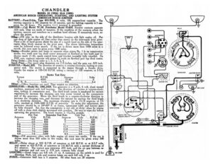
CHANDLER MODEL 33 (1924) 33-A (1925) AMERICAN BOSCH GENERATING, STARTING, AND LIGHTING SYSTEM AMERICAN BOSCH IGNITION : BATTERY.—Prest-O-Lite, Type 613-RHN, 6 volts, 100 oe capacity. The starting capacity is 105 amperes for 20 minutes, and the lighting capacity is 5 am- eres ty 50 hours. The positive (-+-) terminal is grounded. IGNITION :—Coil Model TC-30. Distributor Model FI-635. Breaker contacts separate :020 inch. They are made of tungsten. If the condition of the contacts affect the ignition, remove and resurface on a medium hard oilstone. If excessively worn, re- lace the points. , . : Oiling.—Fill oiler on the side of the distributor housing with light engine oil. Put one drop of light engine oil (less rather than more) on the interrupter lever pivot. Place a bit of hard grease about the size of a match head on the side of the inter- rupter fibre block nearest to the pret post. The above lubricating instructions must be followed every month. If the car is driven more than 1000 miles in a month, this care must be given every 1000 miles. A Timing.—Breaker points just begin to separate when piston No. | is on compression stroke, two teeth past top dead center measured on flywheel or two teeth past in- dicator mark (1:6), spark control lever and breaker assembly fully retarded. On 1925 cars, contacts separate wth piston 1/2 tooth on flywheel past top dead center. Firing Order.—he firing order is 1, 5, 3, 6, 2, 4. Spark Plugs.—The spark plug diameters are 7/8 inches, and the gaps are .020 inch. STARTER.—Model 935. The direction of rotation is counter-clockwise, looking at com- utator end. e starter is connected to the engine through a Bendix drive. anne the engine at 100-150 R.P.M. taking a current of 150 amperes, at 5-514 voits. Starter Test Data .M. Amperes bs: ftiseeazre ee Oiling:—Oilless bearings are used. They require no attention. GENERATOR:—Model No. 1001,1059. The generator is a 4 pole, 6 volt, shunt wound machine, equipped with ball bearings. The direction of rotation is counter-clock- wise, looking at commutator end. The third brush system is employed for current regulation.To increase the charging rate turn screw located on the commutator end of the generator. Move the third brush in a counter-clockwise direction to increase the charging rate, and decrease the out-put by moving the third brush in a clockwise direction. e maximum charging rate is 13-14 amperes, at 7.5 volts, reached at 1500-1600 R.P.M. of armature. To make this adjustment, the generator should be at 50°-80° F. at frame, (generator cold) and battery must be fully charged. See that the commutator is not oily or dirty; clean by wiping off with a clean cloth slightly moistened with gasoline. Be sure to wipe dry before operating the generator. e brush tension is 134-214 pounds. Hot Test Generator Test Data Cold Test Amperes Volts .P.M. Amperes Volts R.P.M. | rer 6.0 ccctt: 600 Oscepesse tas 635 520 peas eee 6.0………… 800 sscecaueaceceseeeee O09 cucee tounge O 8.6 7 6 ie 1200 12. eS ee yf, ae 1200 : | Ye: 1600 fy See if eee 1600 D6 :opswesccscsus: y i Pee 2000 126: sence! TOs caccsnes 2 8.8 ee y | eae 2400 ||) ifs Sumani Da lh 2400 6.0 oo ee Lf « aaa 3200 BiB ke °c | rr 3200 Oiling. —Fill generator oilers with light engine oil every two weeks. If the car is riven more than 500 miles in two weeks, this care must be given every 500 miles. RELAY.—Relay closes at 500 R.P.M. of armature or 6-8 M.P.H. or at 6.5-7 volts, and opens at 450 R.P.M. of armature or 5-6 M.P.H. with a current discharge of -2 amperes. The contact gap separates .015 inch, and the air gap between re- lay armature and coil core is .010 inch, contacts fully closed. . LIGHTING: —Head lamps are 6-8 volt, 21 cp. A resistance on the switch is used for dimming. Dash, tail, side and tonneau lamps are each 6-8 volt, 2 cp. FUSES.—Generator field fuse is 5 amperes. All other fuses are 20 amperes. 1] cS) JUNCTION BLOCK =} upene _ SIDE LIGHT NY, — ry > O HORN BUTTON LIGHTING AND IGNITION SWITCH Cd Vv (@)» TAIL UGHT sc | te BATTERY DIMMER RESISTANCE (Ceres |e DASH LAMP ORORZO}ORORO SWITCH DISTRIBUTOR BREAKER / A NS Pe @ # > oF RY a RET RED a a: = —-——_—— bog ee an ae oe GENERATOR JUNCTION BLOCK XN 1) f} UWS Levene cores a IGNITION COIL I> e B = < a 2 = wi z z ° - G Cay SIDE LIGHT — » STARTING SWITCH