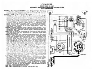
CHANDLER BIG SIX MODEL 35 (1927) DELCO-REMY GENERATING, STARTING AND LIGHTING SYSTEM DELCO-REMY IGNITION BATTERY :—Prest-O-Lite, Type 613-RHK, 6 volt. Starting capacity is 115 amperes for 20 minutes. Lighting capacity is 5 amperes for 20 hours. The positive (+) @/ terminal is grounded. Battery is mounted under the floor boards of the front com- () partment on the right hand frame member. IGNITION: —Coil Model 525-C. Distributor Model 637-X. Breaker contacts separate = .015-.020 inch. They are made of tungsten. Resurface contacts with a fine flat contact file or on a medium hard oilstone. Stationary contact is mounted on cres- cent shaped mounting plate which moves in same arc as breaker arm. This allows setting of contacts without disturbing parallel surface of breaker contacts. To adjust contact opening, loosen lockscrew on crescent mounting plate just back “7 DISTRIBUTOR of stationary contact. Then turn eccentric adjusting screw until correct opening is secured. Tighten the lockscrew. Ignition current is 1-3 amperes with engine running and 3.4-5 amperes with engine stopped. Distributor is semi-automatic. Manual advance is 22°. Automatic advance begins at 400 R.P.M. (engine). Maximum automatic advance of 22° is reached at 2600 R.P.M. Breaker arm spring tension is 15-20 ounces. Mounting :—Distributor is mounted on rear of generator at right of engine. To re- move distributor, disconnect primary lead and remove distributor head with high = tension cables intact. Then loosen lockscrew on side of distributor mounting and lift distributor from place. Oiling:—Refil! the grease cup with medium cup grease and turn down two turns every month or each 1000 miles. Every month put a small bit of vaseline on the face of the breaker cam. Timing: —Breaker contacts begin to separate when the piston entering power stroke reaches a position one-half tooth on the flywheel past top dead center with the manual spark control lever in the fully advanced position. To set timing, crank engine until piston No. | enters compression stroke. This is the upstroke with both valves closed. Fully advance spark control lever and continue to crank engine until piston No. | reaches top PE center. At this point the dead center mark on the flywheel ‘1/6’ will be directly on top of the flywheel and under the center of the flywheel housing. Then crank engine over one half tooth from this point. The breaker contacts should begin to separate. If they do not, loosen advance arm clamp screw and rotate distributor housing until contacts begin to separate. Tighten the clamp screw. Make certain that the rotor button is under the segment connected to the spark plug in cylinder No. 1. On cars with magneto ignition, breaker contacts should be fully open when the iston entering power stroke reaches a position two and one half teeth on the flywheel past top dead center with the spark control lever and breaker assembly in the fully retarded position. To set magneto timing, crank engine until piston RA a No. | reaches firing position. Then loosen coupling at front of magneto and == . aed s: remove breaker box cover and distributor head. Rotate magneto armature until (F)) Pe a ee distributor brush is directly under No. 1 segment. Then turn armature slightly AMMETER < e OROXOROZORO until breaker contacts just begin to separate. Tighten magneto coupling and = replace breaker box cover and distributor head. = Valve Timing:—INLET VALVES:—Head diameter, 1 23/32 inches; stem diam- eter, .372 inch; stem length, 6 9/16 inches; valve lift, 5/16 inch; spring pressure, 60 pounds; tappet clearance, .007 inch recommended. Inlet valves open 2° 'e © before top dead center and close 52° after lower dead center. = EXHAUST VALVES:—Head diameter, | 23/32 inches; stem diameter, .372 inch; 3 se stem length, 6 9/16 inches; valve lift, 5/16 inch; spring pressure, 60 pounds; F tappet clearance, .007 inch recommended. Exhaust valves open 53° before lower ce dead center and close 16° after top dead center. Valve stem guides are not re- j ‘ movable. Oversize valve stems are not made. z= Srine Order:—The firing order is 1-5-3-6-2-4. y= S Plags:—Spark plugs are 74-18 S.AE. Gaps are .025 inch. O Vv CHANDLER BIG SIX MODEL 35 (1927) DELCO-REMY GENERATING, STARTING AND LIGHTING SYSTEM DELCO-REMY IGNITION STARTER:—Model 720-W. Starter is connected to engine through an outboard Ben- dix drive Type R-11X-11T. e direction of rotation is counter-clockwise, look- ing at the commutator end. Starter switch is Model 405-C. Brush spring ten- sion is 24-28 ounces each. Starter Data Torque R.P.M. Volts Amperes OU lb fissverece ees O00 Sscccstscaceshscccccssces Le Loe Fp cate dy ss scnseteconotestneereeed Locks see Hy | tens ieee! 570 Mounting: ges igirg is mounted by special flange mounting at right of engine on forward side of flywheel housing under the flange of the crankcase. To remove starter, disconnect starter cable and remove stud extending through crankcase flange and flange mounting capscrews.