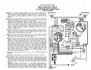
CHANDLER MODEL 65, SERIAL NOS. C-50001 UP PRODUCTION STARTED JULY, 1928 AUTO-LITE GENERATING, STARTING SYSTEM AUTO-LITE IGNITION BATTERY :—Prest-O-Lite, Type A-613-JF. 6 volt, 13 plates. The positive (+) terminal is grounded. Starting capacity (20 minute rate) is 102 amperes for 20 minutes. Lighting capacity (5 ampere rate) is 5 amperes for 20 hours. Battery is mounted under the front floor boards on the left frame member. IGNITION :—Coil Mode! IG-4064. The ignition coil is mounted on a bracket at front of engine block. Ignition current is 2 amperes at 6 volts with engine running and 5 amperes at 6 volts with engine stopped. Distributor Model IGB-4018. Breaker contacts separate .022 inch with breaker arm on lobe of cam. Resurface contacts with a fine flat contact file or on a medium hard oilstone. Contact points may be adjusted by loosening lock nut on stationary point. Breaker arm spring tension is 17-20 ounces. Distributor is full automatic. Automatic advance begins at 400 R.P.M. of engine. Maximum automatic advance is 14 degrees (engine) reached at 2000 R.P.M. Mounting:—Distributor is mounted on accessory bracket at right front of engine. To remove distributor, disconnect primary lead and remove dis- tributor head with cables intact. Then remove set screw on side of dis- tributor shaft and lift distributor from place. Oiling:—Put a few drops of light engine oil in the oil cup on the side of the distributor shaft every month or each 1000 miles. Put a small bit of vase- line on the face of the breaker cam every month. GENERATOR A ARMORED A CAGLE Timing:—Breaker contacts separate when piston entering power stroke reaches a position one tooth past top dead center with the breaker as- sembly in the fully retarded position. To set timing, crank engine over until ((s)) DASH LIGHT piston No. 1 enters compression stroke, This is the upstroke with both ciao valves closed. Continue to crank engine until piston No. 1 reaches top dead center when flywheel mark “DC-1 & 6” will be opposite the indicator mark on the flywheel housing. Continue to crank engine until a position one tooth past top dead center is reached. This is the firing point. If contacts do not separate at this point loosen the clamp screw and rotate the distributor until contacts begin to separate. Tighten the screw and Ei Pao HORN BUTTON Parana JUNCTION BOX IGNITION SWITCH (EtecrROLocK ) PARE Fust. Z + ASOLINE GAUG! yay a Gh GTS . <_ AS Ss make certain that the rotor is opposite the segment connected to the ii = 5 spark plug in cylinder No. 1 and connect the remaining plugs in order o id fp ————————— 5-3-6-2-4 around the distributor head. 2 @/ a NYO Firing Order:—The firing order is 1-5-3-6-2-4. (No. 1 cylinder nearest the radiator.) Spark Plugs:—Spark plugs are %-18 S.A.E. Standard. Gaps are .027 inch. CJ VALVE TIMING:—INLET VALVES:—Head diameter is 1 15/32 inches; stem di- 5 ameter is 5/16 inch; stem length is 5% inches. Tappet clearance is .009 @oe| inch (cold) and .007 inch (hot). Spring pressure is 70 pounds compressed a to 1 17/32 inches. Valve lift is 5/16 inch. Inlet valves open at top dead ( ky) center and close at 54 degrees or 14 teeth on flywheel after lower dead i center. = wey Vv EXHAUST VALVES:—Head diameter is 1 15/32 inches; stem diameter is 5/16 inch; stem length is 5% inches. Tappet clearance is .009 inch (cold) and .007 inch (hot). Spring pressure is 70 pounds compressed to 1 17/32 “a inches. Valve lift is 5/16 inch. Exhaust valves open at 37 degrees or 12 =z teeth before lower dead center and close at 5 degrees or 1% teeth after ©) TAIL LIGHT. Oy, toob DOME LIGHT e) GASOLINE GAUGE TANK UNIT CHANDLER MODEL 65, SERIAL NOS. C-50001 UP PRODUCTION STARTED JULY, 1928 AUTO-LITE GENERATING, STARTING SYSTEM AUTO-LITE IGNITION top dead center. Valve stem guides are removable. Oversize valve stems are not made. ARTER:—Model MN-4015. Starter is connected to the engine through an inboard Bendix drive. The direction of rotation is counter-clockwise, look- ing at the commutator end. Brush spring tension is 24-28 ounces. Starter Data Torque R.P.M. Volts Amperes 41: Ib; ftisccteescccss BOCK ocsspscsiterctsistececsesd , era” ow Ailes} 550 Mounting:—Starter is flange mounted at left of engine on forward side of flywheel housing. To remove starter, disconnect cable and remove 3 flange mounting cap screws. Pull starter forward and lift from place. Oiling:—Put 8 or 10 drops of light engine oil in each of the starter bearings oilers every 1000 miles or each month. ENERATOR:—Model GAL-4115. The direction of rotation is counter-clock- wise, looking at the commutator end. Generator current regulation is by third brush shunt field. To adjust generator output, remove commutator cover band and shift third brush and mounting bracket by tapping on mounting stud with screwdriver. Shift the third brush in a counter-clock- wise direction to increase the charging rate and in the opposite direction. to decrease the charging rate. The third brush is held in any posi