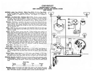
CHEVROLET SUPERIOR MODEL K (1925-26) REMY GENERATING, STARTING AND LIGHTING SYSTEM REMY IGNITION BATTERY :—Exide, Type 3-XC-13-1. Willard, Type XW-13. U. S. L., Type XY-13. 6 volt, 90 ampere hour. Starting capacity is 98 amperes for 20 minutes. The lighting capacity is 5 amperes for 18 hours. The negative (—) terminal is grounde IGNITION: —Coil Model 284-L. Distributor Model 374-A. Breaker contacts separate .030 inch. They are made of tungsten. When the condition of the contacts affects the ignition, remove and resurface on a‘medium hard oilstone or with a fine, flat jeweler’s file. The distributor has no automatic advance. Manual advance is 30°. Mounting :—Distributor is mounted on the generator head and is driven by the gen- erator armature shaft. To remove distributor, disconnect the primary lead and manual advance rod. Remove distributor head with high tension cables intact. Then loosen the clamping bolts through the split collar on the generator housing and lift distributor out. Oiling : —Refill the grease cup on the side of the distributor shaft and turn down one quarter turn every month or each 1000 miles if the car is driven more than 1000 miles in a month. Timing:—Breaker contacts separate when No. 1 piston entering power stroke is at dead center with the spark control lever and breaker assembly in the fully re- tarded position. To check timing, crank engine over until piston No. | enters the compression stroke. This is the upstroke with both valves closed. Fully retard the spark control lever and continue to crank engine until piston reaches top dead center. At this point the top dead center mark on the fywhbel should be opposite the indicator on the flywheel housing. If breaker contacts are not beginning to separate, loosen the lock nut in the center of the breaker cam and pry cam up- ward. Rotate cam until contacts begin to separate. Make certain the cam is correctly seated on taper shaft and tighten the lock nut. Make certain the rotor is opposite the segment connected to the spark plug in cylinder No. | and con- nect the remaining plugs in order 2-4-3 clockwise, around the distributor head. Firing Order:—The firing order is 1-2-4-3. Spark Plugs:—Spark plug gaps are .025 inch. VALVE TIMING:—Inlet Valves. Head diameter is 1 5/16 inches; stem diameter is 7/16 inch; stem length is 4 7/32 inches; tappet clearance is .004 inch. Inlet valves open at 16 degrees after top dead center and close 52 degrees after lower dead center. Exhaust Valves:—Head diameter is 1 5/16 inches; stem diameter is 7/16 inch; stem length is 4 7/32 inches. Tappet clearance is .004 inch. Exhaust valves open 40 degrees before lower dead center and close 16 degrees after top dead center. STARTER:-Model No. 711-BX The direction of rotation looking at the commutator end is counter-clockwise. Starter is connected to motor by a feadix drive. Cranks the at {60 R.P.M. taking 140 amperes. Starter brush tension should be 20-24 ounces each. Starter Data Torque Volts Amperes O Ib. ft. eee LU es 65 VO: cee eeeerserais ra) te 1 eerie 425 Mounting:—Starter is mounted at the right of the engine on the forward side of the flywheel housing. To remove the starter, disconnect cable and flange mounting bolts. Pull starter forward to disengage pinion on drive and lift from place. DIMMER RESISTANCE TASL LICHT SIDE LIGHT @ LIGHTING AND IGNITION SWITCH GENERATOR =r OASH LAMP BATTERY SWITCH HORN BUTTON ©) BREAKER RESISTANCE UNIT == os SIDE LIGHT a . lo }) come Lame STARTING SWITCH NY CHEVROLET SUPERIOR MODEL K (1925-26) REMY GENERATING, STARTING AND LIGHTING SYSTEM REMY IGNITION os Fa 4 or 5 drops of light engine oil into starter oiler every two weeks. If car is driven over 500 miles in two weeks, this care must be given every 500 miles. GENERATOR: -Model No. 950-B. The direction of rotation is counter-clockwise looking at commutator end. The third brush system is used for ME regulation. ¢ maxi- mum charging rate is 18 amperes reached at 1800 R.P.M. of the generator arma- are: Brush tension is 14-18 ounces each. Shunt field current is 5 amperes at 6 volts, Generator Data Amperes Volts eis Amperes Volts R.P.M. AIS, 1 ae 15 bee Av det GO.5. Net kA 1750 C4 | i, a 1750 B.5215.5. cccccsesse oueesene ceceecccneeccce 2500 To adjust the generator charging rate, loosen the generator cover band and the screw on the generator end plate. Then shift the third brush in the direction of armature rotation to increase the charging rate and in the opposite direction to decrease the charging rate. Tighten the screw after making the adjustment. Mounting:—Generator is flange mounted on the right and to the front of the en- gine. Generator is driven by a gear meshing with the camshaft gear housed in the gear case at the forward end of the engine. To remove the generator, remove distributor and ignition coil which is mounted on top of the generator. Remove flange mounting cap screws and pull generator to the rear to disengage the driv- ing gears. Then lift from place. Oilin