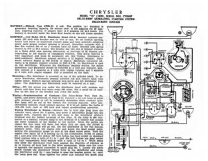
CHRYSLER MODEL “75” (1929), SERIAL NOS. CYOSOP DELCO-REMY GENERATING, STARTING SYSTEM DELCO-REMY IGNITION BATTERY:—Willard, Type CWR-17. 6 volt. The positive (+) terminal is epee eee grounded. Starting capacity (20 minute rate) is 130 amperes for 20 min- utes. Lighting capacity (5 ampere rate) is 5 amperes for 23.4 hours. The (aR) ® GaN battery is mounted under the front floor boards on the left frame member. we wy IGNITION :—Coil Model 525-E. Distributor Model 659-B. Breaker contacts sep- ie arate .022 inch with breaker arm on lobe of cam. To set contact opening, loosen lock screw on stationary contact plate and turn eccentric adjusting screw until proper contact opening is secured. Resurface contacts with a fine flat contact file or on a medium hard oil stone. Breaker arm spring tension is 17.5 to 20.5 ounces. The breaker has two sets of breaker contacts on a three sided cam opening alternately at intervals of 60 degrees cor- responding to 120 degrees of crankshaft rotation. This firing interval is very important and must be accurately set. See Timing. Distributor is semi-automatic. Maximum manual advance is 25 degrees (engine). Auto- matic advance begins at 400 R.P.M. of engine. Maximum automatic ad- vance is 22 degrees (engine) reached at 2900 R.P.M. An Electrolock is used on the distributor. Whenever the distributor requires service, the entire distributor and Elctrolock should be removed as a unit and replaced. Igni- tion current is 2 amperes at 6 volts with engine running and 5 amperes at 6 volts with engine stopped. Coil is mounted on the dash. Mounting:—The distributor is mounted on top of the cylinder block. To re- move distributor, disconnect manual advance rod and remove head with cables intact. Remove manual advance stop screw and lift distributor from place. The distributor and Electrolock must be removed as a unit. Oiling:—Fill the grease cup under the distributor head with medium cup grease and turn down two turns every 500 miles. Put a small bit of vase- , line on the face of the breaker cam every 500 miles. , == icuITION WITCH Timing:—Synchronization of Contacts:—Use Delco-Remy Tool, Part No. ” 7, VIBRATING eseertoued 829751, and follow directions on Page S-25. Connect a six volt lamp in series 5 A CIRCUIT BREAKER with primary circuit at coil to accurately determine when contacts open. : The lamp will go out at the instant the contacts separate. After syn- chronizing contacts, check contact opening. If it is not within the limits of .018-.024 inch, reset at .022 inch and repeat synchronizing operation. Timing Distributor to Engine:—Remove the % inch pipe plug from the cylinder head, above No. 6 piston, and screw a micrometer gauge into the tapped hole. Connect the 6 volt test lamp to the distributor primary terminal and the battery terminal of the relay. If the relay is not con- nected to a battery, connect lamp to one terminal of a battery and ground the other terminal of the battery to the engine. When the points are closed the test lamp will burn, but when they are open the circuit is broken and the lamp will go out. Set the distributor at the full manual advance point. Turn the engine over and locate the dead center point, setting the micrometer gauge on zero at the dead center point. Turn the engine over again till it is coming up on the compression stroke on piston STOP LIGHT SWITCH No 1 and stop with the piston .067 inch before top dead center on standard a) head engines with a ratio of 5.1 to 1 and .004 inch before top dead center Ge ( Ey) ee Ree = ae | Ie on high compression head engines with a ratio of 6.2 to 1. While doing s : Oy, this press the distributor rotor back against the direction of rotation so F sToP Case Gar as to remove all back lash in the drive mechanism. Make sure the rotor LIGHT. Sy BLUE ©) 2 . which clamps the distributor timing lever to the distributor and rotate | the distributor until No 1 cam begins to open the breaker points, i.e., until the lamp goes out. Then tighten the screw and reinstall the spark plug is opposite the segment connected to spark plug No. 1. Loosen the screw {2} wy CHRYSLER MODEL “75” (1929), SERIAL NOS. CYOSOP DELCO-REMY GENERATING, STARTING SYSTEM DELCO-REMY IGNITION wires. To check ignition timing turn over engine two or three times then come up again on No. 1 compression stroke, tapping the crank lightly until the lamp goes out. If the dial reads between the limits of .060 to .075 inch on a standard head engine or .002 to .005 inch on a high compression head engine the timing is satisfactory. If outside these limits, it should be reset. Firing Order:—The firing order is 1-5-3-6-2-4. Spark Plugs:—Spark plugs are Chapion % inch. Gaps are .027-.030 inch. VALVE TIMING:—INLET VALVES:—Head diameter, 154 inch; stem diameter, 11/32 inch; stem length, 6 7/16 inches. Tappet clearance is .005 inch (hot). Spring pressure is 82 pounds with valves open and 52 pounds with valves closed. Valve lift is 5/16 inch. Intake valves open at 6 degrees aft