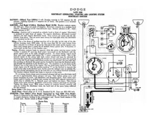
DODGE LATE 1926 NORTHEAST GENERATING, STARTING AND LIGHTING SYSTEM NORTHEAST IGNITION BATTERY.—Willard, Type SJRR-4. 6 volt. Starting capacity is 125 amperes for 20 minutes. Lighting capacity is 5 amperes for 21 hours. The positive (++) terminal is grounded. IGNITION.—Coil Model 17,232-A. Distributor Model 10,786. Breaker contacts separ- ate . inch. They are made of tungsten. Resurface contacts on a medium hard oilstone. Distributor is of the semi-automatic type. Manual advance is 20°. Auto- matic advance is 25°. Mounting.—Ignition coil is mounted on cylinder head at front of engine. Distributor is mounted at right front of engine. To remove distributor, disconnect manual advance rod and remove distributor head. Then remove set screw and litt dis- tributor from place. This set screw must always be kept tight when the distributor is in operation on the car. Oiling.—Put a few drops of medium machine oil in the oiler on the side of the dis- tributor housing every 2000 miles. At the same time lift the rotor button from place and put Lin 3 drops of oil on the felt pad in the center of the breaker cam. Once each season place a small bit of medium heavy grease (No. 4 Keystone or equivalent) on the face of the breaker cam. Timing.—Breaker contacts begin to separate when the piston entering power stroke reaches a position 8° past top dead center (measured on the flywheel) with the spark control lever in the fully retarded position. To check timing, retard spark lever and crank engine until piston No. | enters compression stroke. This is the upward stroke of the piston with both valves closed and may be checked by removing the spark plug and holding the thumb over the opening when the escaping air can be felt. Grane engine until piston reaches top dead center. On cars with igni- tion marking on flywheel, this point can be checked by observing the flywheel mark- ing through the peephole in the flywheel case. The peephole is on the front of the flywheel case at the right of the engine. The top dead center mark is C/1-4. Then crank engine over 8° until the ignition marking “I” on the flywheel is opposite the mark on the edge of the flywheel case. At this point the exhaust valve in cylinder No. 4 is just closing and ignition can be set from this on cars without flywheel markings. The breaker contacts should just begin to separate at this point. To set timing, loosen clamp screw in manual advance rod and turn distributor until oil cup is approximately above advance rod arm. Then tighten clamp screw and loosen mounting set screw. Lift distributor and disengage gears. Then rotate rotor button until it reaches a position just coming into line with segment connected to spark plug in cylinder No. 1. Remesh gears and tighten set screw. Then loosen clamp screw again and turn distributor until breaker contacts just begin to separate. Tighten the clamp screw. With proper setting of contacts breaker contacts will open by rocking the distributor rotor, the back lash of the gears being sufficient for this purpose. Firing Order.—The firing order is 1-3-4-2. Spark Plugs.—Spark plugs are S. A. E. Standard 74-18. Gaps are .025-.030 inch. STARTER.—Type 6304-A (Four Brush) Superseded by Type 6304 (Two Brush). Starter is connected to the engine through a Bendix drive. The direction of rotation is counter-clockwise, tooling at the commutator end. Starter brush tension is 24 pounds each. Starter switch is Model 15380. Starter Data Torque 4 lb. ft 6 “- ne 7 “ 9 “ 12 o DISTRIBUTOR E (0) IGNITION COM |] a S aN. — = Wy ae OROMO)IO see ft -— ; Saag | —- va , e Af – = HORN BREAKER p° avi \ = F I I ry!) it Fe il UL} sii Yr! YY, / CONDENSER TAIL LIGHT DODGE LATE 1926 NORTHEAST GENERATING, STARTING AND LIGHTING SYSTEM NORTHEAST IGNITION Mounting.—Starter is mounted at left of engine by a Standard S. A. E. No. 2 flange mounting. To remove starter, remove four mounting screws and slide starter for- ward from place. Oiling.—Starter bearings are of the oilless type. They require no attention. GENERATOR.—Model LR, Type 6334, Superseded by Type 6334-B. The direction of rotation is counter-clockwise, looking at the commutator end. Generator current regulation is by the third brush system. To adjust charging rate, loosen the screw marked “Lock” on the generator end plate and shift the third brush by turning the other screw marked “Adjust,” located near the lock screw on the generator en plate. Tighten the lock screw after making the adjustment. With standard setting, the maximum charging rate is 15-16 amperes (hot) reached at 1200 R.P.M. of the armature or 23-25 M.P.H. Generator Data Cold Test Hot Test Amperes Volts R.P.M. Amperes Volts R.P.M. eee eee: . NONE Ee aa 510 Bh Lm OD (et LER 620 | by Airey proceed ne esr ee peer ro 700 i ES AEE 800 | | ae 740 lo) Ae eas oe ee 1000 19:6 ccc, | a 1000 J4[5 ae /.. | 1200 Higereoneero Bescon} 200 ND cccescctescietil