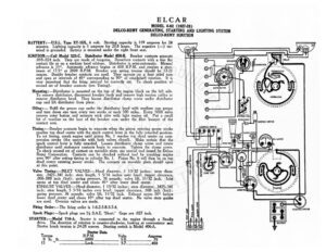
ELCAR MODEL 8-82 (1927-28) DELCO-REMY GENERATING, STARTING AND LIGHTING SYSTEM DELCO-REMY IGNITION BATTERY :—U.S.L. Type XY-15X, 6 volt. Starting capacity is 119 amperes for 20 minutes. Lighting capacity is 5 amperes for 20.8 hours. The negative (—) ter- “ minal is grounded. Battery is mounted under the right front seat. an? SSeS IGNITION: —Coil Model 525-C. Distributor Model 658-B. Breaker contacts separate = 1 —— * .018-. inch. ey are made of funesten, Resurface contacts with a fine flat > : contact file . on a medium hard oilstone. Distributor is semi-automatic. Manual ey advance is 15°. Automatic advance begins at 600 R.P.M. and reaches : i max- imum of 17.5° at 2000 R.P.M. Breaker arm spring tension should be 17-21 ounces. Double breaker contacts are used. ey operate on a four sided cam and open at intervals of 45° corresponding to 90° of crankshaft rotation. It is very important that the firing interval be correctly set. To check position of second set of breaker contacts (see Timing). Mounting:—Distributor is mounted on the top of the engine block on the left side. ’ To remove distributor, disconnect breaker leads and remove high tension cables or remove distributor head. Then loosen distributor clamp screw under distributor cup and lift distributor from place. Oiling:— Refill the grease cup under the distributor head with medium Si grease and turn down one turn every two weeks or eac miles. Every 5000 miles remove rotor button and saturate wick oiler with light engine oil. Put a small bit of vaseline on the face of the breaker cam under the fiber bumper of the contact arm. ae contacts begin to separate when the piston enn power stroke reaches top dead center with the spark control lever in the fully retarded position. To set timing, crank engine until piston No. | reaches top dead center on com- pression stroke (the upstroke with both valves closed). Make certain that the ark control lever is fully retarded. Loosen distributor clamp screw and rotate di istributor until stationary contacts begin to separate. Tighten the clamp screw. To check second set of contact on movable plate, use Saal tool issued by Delco- Remy Corporation. Contacts can be checked without _ tool ae cranking engine over 90° after setting timing in cylinder No. 1. Piston No. 6 will then be on top dead center entering power stroke. The contacts on ie Hee late should open at this point. Valve Timing:—INLET VALVES:—Head diameter, 1 13/32 inches; stem diam- eter, .3425-.341 inch; stem length, 5 5/16 inches over head; tappet clearance, .006-.008 inch (hot); spring pressure, 36 pounds; valve lift, 11/32 inch. Inlet opens at top dead center and closes 45° after lower dead center. EXHAUST VALVES:—Head diameter, | 13/32 inches; stem diameter, .3425-.34] inch; stem length, 5 5/16 inches over head; tappet clearance, .008 inch (hot); spring Fisk pots 36 pounds; valve lift, 11/32 inch. Exhaust opens 50° before lower dead center and closes 10° after top dead center. No valve stem guides are used. Oversize valves are made. Firing Order:—The firing order is 1-6-2-5-8-3-7-4. Spark Plugs:—Spark plugs are 74 S.A.E. ‘Short.’ Gaps are .027 inch. STARTER:—Model 716-A. Starter is connected to the engine through a Bendix drive. The direction of rotation is counter-clockwise, looking at commutator end. Starter brush tension is 24-28 ounces. Starting switch is Model 406-A. Starter Data R.P.M. T Ob. ELCAR MODEL 8-82 (1927) DELCO-REMY GENERATING, STARTING AND LIGHTING SYSTEM DELCO-REMY IGNITION Mounting:—Starter is flange mounted on forward side of flywheel housing at right of engine. To remove starter, disconnect starter cable, r.move three flange mount- ing capsrews and slide starter forward from place. Oiling:—Put 4 or 5 drops of light engine oil in each of the starter bearing oilers every month or each 1000 miles if the car is driven more than 1000 miles in a month. GENERATOR:—Model 949-C. The direction of rotation is counter-clockwise, lookin at the commutator end. Generator current regulation is by third brush shunt field combined with a thermostat. Thermostat contacts open at 150°F. cutting a resist- ance into shunt field circuit and reducing output approximately 40%. $+, adjust generator output, remove commutator cover band and loosen small round headed screw on generator end plate. Then shift third brush in a counter-clockwise direction to increase charging rate and in the opposite direction to decrease charg- ing rate. Tighten the screw after making the adjustment. Generator Data Cold Test Hot Test Amperes Volts R.P.M. Amperes Volts R.P.M. EA Pees aaiiad OS ccreess 1450 OF 22 | fir Gee, ce .2000 Shunt field current is 4 amperes at 6 volts. Generator brush spring tension is 24-28 ounces each. Generator motoring draws 5 amperes at 6 volts. Mounting :—Generator is mounted at forward end of engine on right side by special swinging base bracket and is belt driven. In adjusting belt tension care must be taken not to get belt too tight or excessive wear o