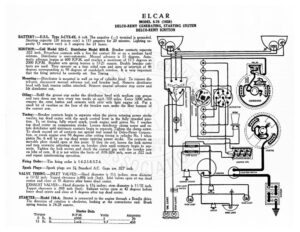
ELCAR MODEL 8-78 (1928) DELCO-REMY GENERATING, STARTING SYSTEM DELCO-REMY IGNITION BATTERY:—U.S.L. Type 3-CVX-6X. 6 volt. The negative (—) terminal is sree Starting capacity (20 minute rate) is 115 amperes for 20 minutes. Lighting ca- pacity (5 ampere rate) is 5 amperes for 21 hours. IGNITION: —Coil Model 525-C. Distributor Model 658-B. Breaker contacts separate 2 inch. Resurface contacts with a fine flat contact file or on a medium hard oilstone. Distributor is semi-automatic. Manual advance is 15 degrees. Auto- matic advance begins at 600 R.P.M. and reaches a maximum of 17.5 degrees at 2000 R.P.M. Breaker arm spring tension is 17-21 ounces. Double breaker con- tacts are used. They operate on a four sided cam and open at intervals of 45 egrees corresponding to 90 degrees of crankshaft rotation. It is very important that the firing interval be correctly set. See Timing. Mounting :—Distributor is mounted in well on top of cylinder head. To remove dis- tributor, disconnect manual advance rod and’ breaker lead. Remove distributor head with high tension cables attached. Remove manual advance stop screw and lift distributor out, Oiling:—Refill the grease cup under the distributor head with medium cup grease and turn down one turn every two weeks or each 500 miles. Every 5000 miles remove the rotor button cd saturate wick oiler with light engine oil. Put a small bit of vaseline on the face of the breaker cam under the fiber bumper of the contact arm. Timing:—Breaker contacts begin to separate when the piston entering power stroke reaches top dead center with the spark control lever in the fully retarded posi- tion. To set timing, fully retard spark, crank engine until piston No. | reaches top dead center on compression stroke. Loosen distributor clamp screw and ro- tate distributor until stationary contacts begin to separate. Tighten the clamp screw. To check second set of contacts use special tool issued by Delco-Remy Corpora- tion, or crank engine over 90 degrees after setting timing in cylinder No. | when piston No. 6 will be on top dead center entering power stroke. The contacts on movable plate should open at this point. If they do not, loosen the lock screws and turn eccentric adjusting screw on breaker plate until contacts begin to sep- arate. Tighten the lock screws and check the contact gap with the breaker arm on lobe of cam. If it is not within the limits of .018-.024 inch, reset at .022 inch and repeat synchronizing operation. Firing Order:—The firing order is 1-6-2-5-8-3-7-4, Spark Plugs:—Spark plugs are 74 Standard A.C. Gaps are .027 inch. VALVE TIMING:—INLET VALVES:—Head diameter is 1!4 inches; stem diameter is 11/32 inch. Tappet clearance is.006 inch (hot). Inlet valves open at top dead center and close at 35 degrees after lower dead center. EXHAUST VALVES:—Head diameter is 13% inches; stem diameter is 11/32 inch. Tappet clearance is .008 inch (hot). Exhaust valves open at 42 degrees before ower dead center and close at 5 degrees after top dead center. STARTER :—Model 716-A. Starter is connected to the engine through a Bendix drive. e direction of rotation is clockwise, looking at the commutator end. Brush spring tension is 24-28 ounces. Starter Data R.P.M. Volts Torque IGNITION SWITCH STOP LIGHT = Ce) Switch EE es ELCAR MODEL 8-78 (1928) DELCO-REMY GENERATING, STARTING SYSTEM DELCO-REMY IGNITION Mounting:—Starter is mounted at right of engine on forward side of flywheel hous- ing. To remove starter, disconnect cable and starting pedal rod. Then remove cap screws on flange and lift starter forward and out. Oiling:—Put 4 or 5 drops of light engine oil in the starter bearing oilers every month or each 1000 miles. GENERATOR:—Model 949-C, The direction of rotation is counter-clockwise, looking at the commutator end. Generator current regulation is by third brush shunt field and thermostat. Thermostat contacts open at 150 degrees F. cutting a re- sistance into shunt field circuit and reducing output 40%. To adjust generator output, remove commutator cover band and loosen small round headed screw on generator end plate. Shift third brush in a counter-clockwise direction to increase the charging rate and in the opposite direction to decrease the charging rate. Tighten screw after adjustment. Generator Data Cold Test Hot Test Amperes Volts R.P.M. Amperes Volts R.P.M. 19-21 sce parse 85 sue ees 1450 O12. el. ’/] se 2000 Shunt field current is 4 amperes at 6 volts. Spring tension is 24-28 ounces each. Generator motoring, draws 5 amperes at 6 volts. Mounting: —Generator is flange mounted at right of engine on rear of timing chain case. To remove generator, loosen mounting bracket screws. Push generator and water pump towards crank case and pry off belt. Remove water connections to pump, take out generator mounting screws, and lift out generator and pump as- sembly. Radiator must be drained before the pump can be removed. ! RELAY:—Model 265-B. Relay is mounted on the generator. Contacts close when the voltage