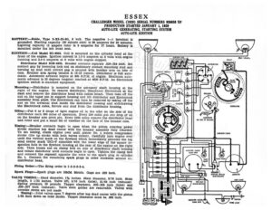
ESSEX CHALLENGER MODEL (1929) SERIAL NUMBERS 928658 ‘UP PRODUCTION STARTED JANUARY 1, 1929 AUTO-LITE GENERATING, STARTING SYSTEM AUTO-LITE IGNITION BATTERY:—Exide, Type 8-XI-13-IG, 6 ‘volt. The negative (—) terminal is grounded. Starting capacity (20 minute rate) is 98 amperes for 20 minutes, Lighting capacity (5 ampere rate) is 5 amperes for 17 hours, Battery. is Cas (ay) mounted under the left front seat. PU Ay,. RYE IGNITION:—Coil Model IG-4065. Coil is mounted on the cylinder head at the front of the engine. Ignition current is 1.5-3 amperes at 6 volts with engine running and 3.4-5 amperes at 6 volts with engine stopped. Distributor Model IGB-4022. Breaker contacts separate .020-.024 inch. Set . DISTRIBUTOR i contact gap by loosening lock nut on stationary contact mounting stud and a turning up stud until correct gap is secured with breaker arm on lobe of * cam. Breaker arm spring tension is 16-20 ounces. Distributor is full auto- for matic. Automatic advance begins at 800 R.P.M. of engine. Maximum auto- / matic advance is 20 degrees (engine) reached at 4000 R.P.M. An Electrolock ignition switch is standard equipment, Mounting:—Distributor is mounted on the accessory shaft housing at the right of the engine. To remove distributor, disconnect Electrolock at the dash and remove the distributor head with cables intact. Then take off the nut on the taper pin in support housing and lift distributor and Electrolock assembly from place. The Electrolock can then be removed by taking off the nut on the terminal stud inside the distributor housing and withdrawing the Electrolock cable, ferrule and stud from the distributor housing, Oiling:—Put 6 or 8 drops of light engine oil in the oiler on the side ‘of the distributor each 500 miles of operation. Every 250 miles put one drop of oil on the breaker arm pivot pin. Every 5000 miles remove the distributor. Head and rotor and put a small bit of vaseline on the face of the breaker cam. TANK UNIT > OIL GAUGE = CONDLHSER 5 OM SIDE OF HOUSING F Timing:—Breaker contacts begin to open when the piston entering power Stroke reaches top dead center with the breaker assembly fully retarded. To set timing, crank engine over until piston No. 1 enters compression stroke (the up stroke with both valves closed). Carefully turn engine over until the vertical mark on the flywheel which immediately precedes the top dead center mark ‘DC1-6’ coincides with the lower edge of the square in- spection hole in the flywheel housing at the rear of the engine on the right side. Then loosen nut on clamp bolt on side of distributor shaft housing and rotate distributor until contacts begin to open. Tighten the clamp bolt and connect the segment opposite the rotor to the spark plug in cylinder No. 1. Connect the remaining spark plugs in order clockwise around the distributor head. FY ARMORED CABLE GASOLINE GAUGE DASH UNIT Firing Order:—The firing order is 1-5-3-6-2-4, Spark Plugs:—Spark plugs are 18MM. Metric. Gaps are .025 inch. sa . y | ere IGNITION SWITCH AMMETER ELECTROLOCK VALVE TIMING :—Head diameter, 13 inches. Stem diameter, 5/16 inch. Stem eT, length, 5 1/32 inches. Valve lift, 5/16 inch (inlet), 21/64 inch (exhaust) Tl Spring pressure, 50 pounds. Tappet clearance, .003-.005 inch (inlet) and 005-.007 inch (exhaust). Valve stem guides are removable. Valves with oversize stems are not made. – Timing :—Inlet valves open 7 degrees after top dead center with the piston Ps 1/64 inch down on inlet stroke. Tappet clearance must be .006 inch. -Gagoumne cauce Uh 7 T swircn “TANK UNIT On DOME LIGHT | (Gham Ls Ee 7 ( | ESSEX CHALLENGER MODEL: (1929)’ SERIAL NUMBERS 928658 UP PRODUCTION STARTED JANUARY: 1, 1929 AUTO-LITE GENERATING, STARTING SYSTEM _ AUTO-LITE IGNITION STARTER :—Model MZ-4012. Starter is connected to the engine through an in- board Bendix drive. The direction of rotation is counter-clockwise, viewed from the commutator end. ‘Brush spring tension is 244 pounds. Starter Data Torque 12.2 “ Mounting:—Starter is mounted by special flange at left of engine on forward side of flywheel housing. To remove starter, disconnect cable and lead to junction block. Then remove ‘three flange mounting cap screws, pull starter forward to clear Bendix and lift from place. Oiling:—Starter bearings are oilless. They require no attention. GENERATOR :—Model GAM-4101. The direction.of rotation is counter-clockwise, viewed from the commutator end. Generator current regulation is by third brush shunt field. To adjust generator output, remove the commutator cover band and shift the third brush by tapping on the mounting stud with a screwdriver. Shift the third brush in a counter-clockwise direction to in- crease the charging rate and in the opposite direction to decrease the charging rate. The brush is held in position by friction between the mount- ing stud and the end plate. With standard car setting, the maximum charg- ing rate is 15 amperes at 8 volts reached at 1350 R.P.M. or 25 miles per hour. Generator Dat