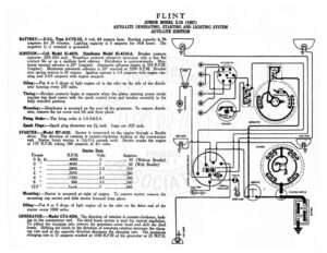
FLINT JUNIOR MODEL Z-18 (1927) AUTO-LITE GENERATING, STARTING AND LIGHTING SYSTEM AUTO-LITE IGNITION BATTERY:—U.S.L. Type 3-CVX-5X, 6 volt, 84 ampere hour. pares god is 96 amperes for 20 minutes. Lighting capacity is 5 amperes for 16.8 hours. The negative (—) terminal is grounded. IGNITION:—Coil Model IG-4070. Distributor Model IG-4118-A. Breaker contacts separate .020-.024 inch. Resurface contacts whenever necessary with a fine flat contact file or on a medium hard oilstone. Distributor is semi-automatic. Max- imum manual advance is 20° (engine). Automatic advance begins at 350 R.P.M. (engine). Maximum automatic advance is 20° reached at 3200 R.P.M. Breaker arm spring tension is 20 ounces. Ignition current is 1-3 amperes with engine run- ning and 3.4-5 amperes with engine stopped. Oiling:—Put 4 or 5 drops of light engine oil in the oiler on the side of the distrib- utor housing every 250 miles. Timing :—Breaker contacts begin to separate when the piston entering power stroke reaches top dead center with the spark control lever and breaker assembly in the fully retarded position. Mounting: —Distributor is mounted on the rear of the generator. To remove distrib- utor, remove the set screw and lift unit from place. Firing Order:—The firing order is 1-5-3-6-2-4. Spark Plugs:—Spark plug diameters are 74 inch. Gaps are .025 inch. STARTER:—Model MP-4102. Starter is connected to the engine through a Bendix drive. e direction of rotation is counter-clockwise, looking at the commutator end, Starter brush tension is 1/4-11/2 pounds each. Starter cranks the engine at 175 R.P.M. taking 180 amperes at 4.5 volts. Starter Data Torque R.P.M. Volts Amperes 02 Ihss feiss O00 eee Le . 45 (Without Bendix) OO peepee QQ seresere cn seeecuscses 5 A FZ. 50 (With Bendix) Uh rccceccacece! //;| | | rear BNNs Mo 150 Bis scsasusesesuscaneseas 7. | || oe neem 5 cn Ne ..200 ye seasabisesssliciucuns 1320.0… ecececeseoeee 45 ccceshcs ees 300 Be neceoceescenccshteane 11) | 35 eS ..500 125 czas e Lock………cseceeceeee 5 een enn, 2 650 Mounting:—Starter is mounted at right of engine. To remove starter, remove the mounting cap screws and slide starter forward from place. Oiling:—Put 4 or 5 drops of light engine oil in the oiler on the drive end of the starter every 1000 miles. GENERATOR:—Model GYA-4204. The direction of rotation is counter-clockwise, look- ing at the commutator end. The third brush system is used for current regulation. To adjust the charging rate, remove the generator cover band and shift the third brush. Shifting the brush in the direction of armature rotation increases the charg- ing rate and in the opposite direction decreases the charging rate. The maximum charging rate is 15 amperes reached at 1500 R.P.M of the generator or 25 M.P.H. DISTRIBUTOR . § RESISTANCE Ww) DOME LAMP Sa IT ‘ wereees ha iets ~ 7 SS ~ =~ a 42a STARTING SWITCH ew FLINT JUNIOR MODEL Z-18 (1927) AUTO-LITE GENERATING, STARTING AND LIGHTING SYSTEM AUTO-LITE IGNITION Oiling:—Put 4 ck 5 drops of light engine oil in each of the generator bearing oilers Generator Data hn ac ih (78°) RPM ha Hot Val (240°) RPM, every 100 res olts 5 eres olts . 0. saveeeee 0.4 RO 0 senecenecnneeneeesOn i. ee 650 RELAY :—Model CB-4007. Rey: is geet on top of the generator. Relay contacts : oreecersereee| Xn 720 close at 550 R.P.M. or 9 H. when the voltage of the generator reaches 7-7.5 1Ossocorrces ya 1200 volts and open at 8 M.P.H. with a discharge current of 1!42-2/ amperes. Charg- _. _. 12… 79. 1700 ing current at closing of contacts is 0-2 amperes. Contacts separate .025-.035 12 “7.6 2200 10… y by a ae 2400 inch. Air gap between relay armature and coil core is .010-.030 inch, contacts veers freely at 150 R.P.M. as — 45 se lie at 6 —. ¥ ay, losed, field current is 3.25 amperes at 6 volts. Generator brush tension should be | LiGHTING:—Clam Switch Model 10544. Head lamps are each, 68 volt, 21 ep. S.C Dash, tail, side and dome lamps are each 6-8 volt, 3 cp. Mounting:—Generator is mounted at right of engine by a bell housing. To remove, remove mounting cap screws and lift generator from place. FUSES:—Lighting fuse is 20 amperes.