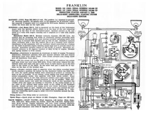
FRANKLIN MODEL 135 (1929) SERIAL NUMBERS 183,000 UP MODEL 137 (1929) SERIAL NUMBERS 183,000 UP PRODUCTION STARTED JANUARY 5, 1929 DELCO-REMY GENERATING, STARTING SYSTEM DELCO-REMY IGNITION BATTERY :—U.S.L. Type XY-19X-6, 6 volt. The positive (+) terminal is ground- ed. Starting capacity (20 minute rate) is 153 amperes for 20 minutes. Light- ing capacity (5 ampere rate) is 5 amperes for 27.6 hours. Battery is mounted under the front seat on the right side. (rn) (om) IGNITION:—Coil Model 528-X. Coil is mounted on the back of the instrument board with the ignition switch which is in the base of the coil extending ELLOW —rarrenhe! through to the face of the instrument panel. Ignition current is 134 am- FENDER LIGHT b 1 sea a peres at 6 volts with engine running and 4 amperes at 6 volts with engine — antinie stopped. >/ (e) : Distributor Model 640-T. Breaker contacts separate .018-.024 inch. Set (om) NS (en) contact gap by loosening lock screw on stationary contact mounting plate RAY ; directly behind the breaker arm and turning eccentric adjusting screw until > — x correct gap is secured with breaker arm on lobe of cam. Resurface contacts Py when necessary with a fine flat contact file or on a medium hard oilstone. Distributor is full automatic with an auxiliary retard controlled by a button on the dash to prevent engine laboring under load and to provide retard for starting. Automatic advance begins at 400 R.P.M. of engine. Maximum au- tomatic advance is 39 degrees reached at 2400 R.P.M. of engine. Breaker arm spring tension is 17-21 ounces. DIMMING RESISTANCE CARBURETOR FUEMER Mounting :—Distributor is mounted on crankcase at right of engine. To remove distributor, disconnect primary lead and manual advance rod and remove 5 —- distributor head with cables intact. Then loosen advance arm clamp screw © co Co.) and lift distributor from place. | a Oiling:—Fill the grease cup on the side of the shaft with medium cup grease COUPLING 80x G: and turn down one turn every 2000 miles. Every 1000 miles, remove the dis- re | tributor head and rotor and put a few drops of light engine oil in the wick