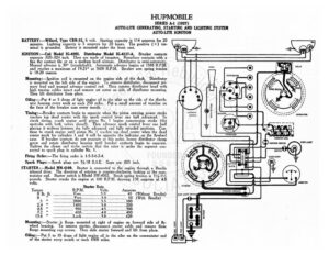
HUPMOBILE SERIES A-1 (1927) AUTO-LITE GENERATING, STARTING AND LIGHTING SYSTEM AUTO-LITE IGNITION BATTERY :—Willard, Type CRR-15, 6 volt. Starting capacity is 114 amperes for 20 minutes. Lightin sapecity is 5 amperes for 20 hours. The positive (+) ter- minal is Foi attery is mounted under the front seat. IGNITION :—Coil Model 1G-4065. Distributor Model IG-4117-A. Breaker contacts separate .020-.024 inch. They are made of tungsten. Resurface contacts with a fine flat contact file or on a medium hard oilstone. Distributor is semi-automatic. Manual advance is 30° (crankshaft). Automatic advance begins at 1500 R.P.M. and reaches a maximum of 19-21° at 3600 R.P.M. Breaker arm spring tension is 18-20 ounces. Mounting:—Ignition coil is mounted on the engine side of the dash. Distributor is mounted on the left side of the engine. To remove distributor, disconnect pri- mary lead and manual advance control rod. Then remove distributor head with high tension cables intact and remove set screw on side of distributor mounting. Then lift distributor from place. Oiling:—Put 4 or 5 drops of light engine oil in the oiler on the side of the distrib- utor housing every week or each 250 miles. Put a small amount of vaseline on the face of the breaker cam every month. Timing: —Breaker contacts begin to separate when the piston entering power stroke reaches top dead center with the spark control lever one half advanced. To check timing, crank engine until piston No. 1 begins compression stroke (the upstroke with both valves closed). Then advance spark control lever one half placing it midway between the fully advanced and fully retarded positions. Con- tinue to crank engine until piston No. | reaches top dead center when the dead center mark for cylinders | and 6 will be opposite the indicator on the flywheel case. If breaker contacts do not separate at this point, loosen distributor clamp screw and rotate distributor housing until breaker contacts begin to separate. Tighten the clamp and make certain that the rotor is under the segment con- nected to spark plug in cylinder No. 1 Firing Order:—The firing order is 1-5-3-6-2-4. Spark Plugs:—Spark plugs are 74-18 S.A-E. Gaps are .025 inch. STARTER :—Model MN-4109. Starter is connected to the engine through a Bendix inboard drive. The direction of rotation is counter-clockwise, looking at the com- mutator end. Starter switch is Model SW-4002. Brush spring tension is ale pcan: Starter cranks the engine at 160 R.P.M. drawing 130 amperes at volts. Starter Data Torque R.P.M. Volts Amperes 0 Ibs ft) ke Sac Bree vicccccscsssscsccss 5.08 heat 45 (Without Bendix) O00 So Yee Rreeccnscaees: 5 Oe een 50 (With Bendix) Bs ccrcccconsatees 2800… .soeeeseeees DD eerreccse crea 100 DAT pecziesicisssrass 1450: Scere 5 Oech ecies .200 oA HO eee serer r 95 0 eescl esc y fe Ferareorriyemere 300 y (es (o>) | AL eee 13:6 ™ Wea Lock sscccscsciee BO bercccteent: 620 Mounting:—Starter is flange mounted at right of engine on forward side of fly- wheel housing. To remove starter, disconnect starter ca e and remove three flange mounting cap screws. Then slide starter forward and lift from place. Oiling:—Put 5 to 10 drops of light engine oil in the oiler on the commutator end of the starter every month or each 1000 miles. ~ HORN | DISTRIBUTOR re eet ed – ©Oi©® © © © © © HORN BUTTON kK ANAL | aT TT “IGNITION COL (3) IGKMON SwiTcR DOME LICHT DASH LIGHT prom 1. ve (5) 7 AMMETER STOP LIGHT TAIL LIGHT C G HUPMOBILE SERIES A-1 (1927) AUTO-LITE GENERATING, STARTING AND LIGHTING SYSTEM AUTO-LITE IGNITION GENERATOR:—Model GJ-4201. The direction of rotation is counter-clockwise, look- ing at the commutator end. Generator current regulation is by third brush shunt field, To adjust generator output, remove commutator cover band and shift third brush by tapping on third brush mounting stud with a screwdriver. Shift the third brush in a counter-clockwise direction to increase the ag te rate and in the opposite direction to decrease the charging rate. The third brush is held in any position by friction between the third brush mounting stud and the penerater endplate. The maximum charging rate is 16 amperes reached at 1600 R.P.M. Generator Data Cold Test Hot Test Amperes Volts .P.M. Amperes Volts | eRe Naeeecs OS sacipsesreccoss 600 OD scsi A Obes 5 10 1254 i Ae A el Generator motoring draws 5 amperes at 6 volts. Shunt field test current is 2 amperes at 6 volts directly across field terminals. Each coil tested separately draws 8.8 amperes at 6 volts. Brush spring tension is 114-114 pounds each. Mounting:—Generator is flange mounted at right of engine on rear side of timing chain case. To remove generator, disconnect generator lead and loosen timing chain adjustment set screw. Then remove three flange mounting cap screws and slide generator to the rear, being careful not to disturb timing chain adjustment. Generator is driven by timing chain. e chain may be adjusted by loosening three flange cap screws on generator and shiftin