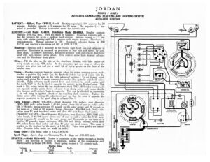
JORDAN MODEL J (1927) AUTO-LITE GENERATING, STARTING AND LIGHTING SYSTEM AUTO-LITE IGNITION BATTERY :—Willard, Type CWR-15, 6 volt. Starting capacity is 114 amperes for 20 minutes. Lighting capacity is 5 amperes for 20 hours. The negative (—) ter- minal is acct 7 | Battery is mounted under the driver’s seat. IGNITION: —Coil Model IG-4078. Distributor Model 1B-4004A. Breaker contacts separate .018-.022 inch. They are made of tungsten. Resurface contacts with a fine flat jeweler’s file or on a medium hard oilstone. Ignition current is 1.3 am- peres with engine running and 3-4.5 amperes with engine stopped. Distributor is semi-automatic. Manual advance is 14°. Automatic advance begins at 200 R.P.M. and reaches a maximum of 14° at 2800 R.P.M. Mounting: Ignition coil is mounted in the frame, right hand side rail adjacent to generator. Distributor is mounted on generator at rear end and driven by arm- ature shaft. To remove distributor, disconnect primary lead and remove distributor head with high tension cables intact. Then remove screw from manual advance arm and lift distributor from place. Oiling:—Fill the oiler on the side of the distributor housing with light engine oil every month or each 1000 miles. At the same,time put one drop of oil on the breaker arm pivot pin and put a small bit of heavy grease on the face of the breaker cam. ‘ Timing: —Breaker contacts begin to separate when the piston entering power stroke reaches a position 14, inches (on the flywheel) before top dead center with the manual spark control lever in the fully advanced position. To set timing, crank engine until piston No. | enters compression stroke (the upstroke with both valves closed). Fully advance spark control lever and continue to crank engine until the mark ‘IGN’ on the flywheel is opposite the pointer in the flywheel case. This mark is 114 inches before the top dead center mark ‘D.C.’. If breaker contacts do not separate at this point, loosen advance lever clamp screw and rotate distrib- utor housing until contacts begin to separate. This cart be checked by connecting a six volt lamp in ignition circuit or by watching dash ammeter. Tighten the clamp screw after making the adjustment and see that the rotor is opposite the segment connected to the spark plug in cylinder No. 1. Valve Timing:—INLET VALVES:—Head diameter, 1’4 inches; stem diameter, -3095-.3085 inch; valve length, 5 61/64 inches (from top of seat to end); valve lift, 5/16 inch; spring pressure, 61 pounds on the outer spring and 26 pounds on the inner or a total of 87 pounds; tappet clearance, .006-.004 inch (hot); inlet valves open 8° past top dead center and close 40° past lower dead center. EXHAUST VALVES :—Head diameter, 13% inches; stem diameter, .3095-.3085 inch; valve length, 5 61/64 inches (from top of seat to end); valve lift 5/16 inch; spring pressure, 61 pounds on the outer spring and 26 pounds on the inner or a total of 87 ‘iow tappet clearance, .006-.004 inch (hot); exhaust valves open 40° before lower dead center and close 8° after top dead center. This point is marked on the flywheel by the mark ‘+-1-EX.CL’. Valve stem guides are remov- able. Oversize valve stems are made on order. Firing Order:—The firing order is 1-6-2-5-8-3-7-4, Spark Plugs:—Spark plugs are Champion No. 4. Gaps are .030-.025 inch. STARTER:—Model MUA-4003. Starter is connected to the engine through a Bendix drive. The direction of rotation is clockwise, looking at the commutator end. Starter switch is Model SW-3646. Brush spring tension is 1!/ pounds each. Starter Data R.P.M. Amperes 2a) “it-—@ qt HORN BUTTON DISTRIBUTOR ®® ©@@© ©© ©®@ / s SS NY AN onl cy YY 4 ‘fof C4 of oe 3) Woo Cay BREAKER CONDENSER IGNITION SWITCH AMMETER JORDAN MODEL J (1927) AUTO-LITE GENERATING, STARTING AND LIGHTING SYSTEM AUTO-LITE IGNITION Mounting:—Starter is flange mounted at left of engine on forward side of flywheel housing. To remove starter, disconnect starter cable and remove three flange mounting bolts. Then slide starter forward from place. Oiling:—Starter bearings are oilless. They require no attention. GENERATOR:—Model GAB-4002. The direction of rotation is counter-clockwise, oon, at the Comintstor end. Generator current regulation is by third brush shunt field a bol enerator output, remove the commutator cover band and shift the third Ra mounting plate by tapping on the mounting stud with a screwdriver. Shift the third brush in a counter-clockwise direction to increase the charging rate and i in the opposite direction to decrease the charging rate. Max- imum charging rate is 17.5 amperes reached at 1300 R.P.M. or 25 M.P.H Generator Data Cold Test Hot Test Amperes Volts R.P.M Amperes Volts R.P.M. ee i oe ee 630 , a nt TY ee 750 {ee y fe, Poona 780 YO.fBe-wcasee Lie a 1000 ee 1, 950 53! Be M….A 80. Lyerveverevere 1400 dD cxsnssarseeree | en 1300 [i eee f 7 A fen TO 2000 3 ccs 1 Brcse5 ee 1950 Generator motoring draws 6 amperes at 6 volts. Shunt field current is 6.6 am- peres at 6 volts. Brus