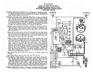
KISSEL MODEL 6-73, SERIAL NOS. 73-1000 UP PRODUCTION STARTED AUGUST 15, 1928 DELCO-REMY GENERATING, STARTING SYSTEM DELCO-REMY IGNITION BATTERY :—Willard, Type CWR-13, 6 volt. The positive (+) terminal is ground- ed. Starting capacity (20 minute rate) is 98 amperes for 20 minutes. Light- ing capacity (5 ampere rate) is 5 amperes for 16.8 hours. The battery is (7) Ay) cradle mounted under the front seat. Y 5) IGNITION :—Coil Model 528-C. Distributor Model 640-L. Breaker contacts sep- = + of 1 arate .018-.024 inch with breaker arm on lobe of cam. Resurface contacts with a fine flat contact file or on a medium hard oilstone. Adjust contact HORN pe ae gap by loosening lock screw on stationary contact plate and shifting plate | SRY : by turning eccentric adjusting screw until proper contact is secured. Break- | owe ‘ ARS er arm spring tension is 17-21 ounces. Distributor is semi-automatic. Man- _ ual advance is 15 degrees (engine). Automatic advance begins at 400 R.P.M. if of engine and reaches the maximum of 20 degrees at 2200 R.P.M. Mounting:—Coil is mounted on the dash. Distributor is mounted on the cyl- inder head with a SAE Type B mounting. To remove the distributor, dis- DISTRIBUTOR connect primary lead and manual advance rod. Remove distributor head LIGHTING SWITCH with high tension cables intact. Loosen the hold-down screw and lift dis- Wee tributor from place. At Oiling:—Fill the grease cup on the side of the distributor shaft with medium cup grease and turn down one turn every 500 miles. Put a small bit of vas- eline on the face of the breaker cam and a drop of light engine oil on the breaker arm pivot every 1000 miles. Put a few drops of light engine oil in | DIMMER RESISTANCE the wick oiler under the rotor every 2000 miles. Timing:—Breaker contacts separate when the piston entering power stroke reaches a position 10 degrees after top dead center (measured on the fly- wheel) with the spark control in the fully retarded position. To check tim- ing, crank engine over until piston No. 1 is coming up on the compression stroke. This is the up stroke with both valves closed. Fully retard the spark. Continue to crank the engine until piston reaches the firing position when the ignition mark ‘1&6’ on the flywheel will be 10 degrees past the indicator on the flywheel housing. Breaker contacts should separate at this point. If they do not, loosen the clamp screw on the side of the distffbutor mounting and rotate distributor until contacts separate. Tighten the screw. Make certain that the rotor is opposite the segment connected to the spark plug in cylinder No. 1 and connect the remaining plugs in order 5-3-6-2-4 around the distributor head. Firing Order:—The firing order is 1-5-3-6-2-4. No. 1 cylinder nearest the = radiator. u Spark Plugs:—Spark plugs are 7%-18 Long. Gaps are .030 inch. VALVE TIMING :—INLET VALVES:—Head diameter, 1 17/32 inches. Stem diam- eter, .342 inch. Stem length, 5 15/16 inches. Tappet clearance, .008 inch (hot). Spring pressure, 85 pounds. Valve lift, 11/32 inch. Inlet valves open at top dead center and close 54 degrees after lower dead center. EXHAUST VALVES:—Head diameter, 1 13/32 inches. Stem diameter, .342 inch. Stem length, 5 15/16 inches. Tappet clearance, .008 inch (hot). mer Spring pressure, 85 pounds. Valve lift, 11/32 inch. Exhaust valves open at 50 degrees before lower dead center and close 10 degrees after top dead cen- t A cisely ON ey, ter. Valve stem guides are removable. Oversize valves are not made. STARTER:—Model 716-A. Starter is connected to the engine through a Bendix OOO) Ws ucHT 2 drive. The direction of rotation is clockwise, viewed from the commutator i — HORN BUTTON ()) SIDE LIGH’ ELECTRIC CLOCK Gas pean | JUNCTION – TERMINAL © Cer} JUNCTION BLOCK STOP LIGHT. KISSEL MODEL 6-73, SERIAL NOS. 73-1000 UP PRODUCTION STARTED AUGUST 15, 1928 DELCO-REMY GENERATING, STARTING SYSTEM DELCO-REMY IGNITION end. Starter cranks the engine at 150 R.P.M. drawing 175 amperes at 4.5 volts. Brush spring tension is 24-28 ounces. Starter Data Torque R.P.M. Volts Amperes BTCC: cssccccxacsisnacncmes SOOO sscscssccccisseiccsseesssesced L,Y | eeetariteeeeeeeenrer cee ee 70 15 b> feos LOCK Soc ae es > Hy Prenieenecersecnpsene ETE 450 Mounting:—Starter is mounted with a SAE No. 1 flange mounting on the right of the engine on the forward side of the flywheel housing. To remove start- er, disconnect cable and remove flange mounting cap screws. Then pull starter forward and lift from place. Oiling:—Put 8-10 drops of light engine oil in the oiler on the commutator end of the starter every 1000 miles. The drive end bearing is oilless and requires no attention. Every six months remove the plug in the reduction gear case and repack the gear compartment with graphite grease. GENERATOR:—Model 955-H. The direction of rotation is counter-clockwise, viewed from the commutator end. Generator current regulation is by third brush shunt field and thermostat. Thermostat contacts open at 160 degrees F. c