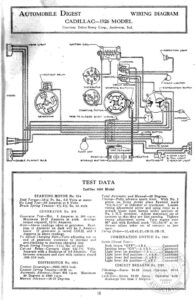
AUTOMOBILE DIGEST IQMITPIOM COW PoC UTESUT BELAY LE AEA FLOAT UNIT POSITIVE BYORAGT BATTIANY WIRING DIAGRAM CADILLAC—1926 MODEL Courtesy Delco-Remy Corp., Anderson, Ind. Dh Caeicanesg AAROUIY SREAKE! STARTING Seton { EGATIVE Switches TEST DATA Cadillac 1926 Model STARTING MOTOR No. 314 Stall Torque—18% Ft. ths., 3.2 Volts at motor. No Load Test—-60 Amperes at 6 Volts. Brush Spring Tension—24-2% lbs. on each. GENERATOR No. 315 Generatoy Test—Hot. 2 Amperes at 500 r.p.m. Maximum 15-17 Amperes at peak. Average output required, 12-14 Amperes. Note—Above readings taken at generator. Read- ings at Ammeter on dash will be 2 Amperes lower. If generator is tested COLD, add 2 Amperes to above readings. To Adjust Charging Rate Tarn adjusting nut on end of. generator clockwise te increase and anti-clockwise to decrease charging rate. _ Brush Spring Tension—1-144 bs. on each. Cut-eut Relay—Contacts close 634-714 Volts. Separate with a discharge of 0-8 Amperes. Gap between armature and core with contacts closed .009-.010° inch. DISTRIBUTOR No. 5281 Contact Separation—.0225-.0275 inch. Contact Spring Tension—16-20 oz. Automatic Advance—Start 600 r.p.m. 8) Degrees at 2800 r.p.m. Maxual Advence—18-22 Degrees, Maximum prapaecteser atrovent pot) ~— Total Automatic and Manual—52 Degrees. Timing-—Fully advance spark lever. With No. 1 piston on firing stroke place flywheel mark “1G/A-1/5” at indicator or crankcase. Loosen timing adjustment screw and using rotor as a wrench locate rotor button under position of No. 1 H.T. terminal. Adjust stationary set of contacts so that they are just opening. Tighten timing adjustment screw. Turn engine over 90° and with flywheel mark “1G/A2/6” at in- dicator adjust other set of contacts to just open, Miring Order—iL-4R-4L-21L-3R-2.2R-1R. COMBINATION SWITCH No. 1284 Swith Circuit Test— Both levers “OPF’—4&5………. Connected Tgnition lever “ON”—1, 2&3….0, Connected Light lever 1st position—7 & 47… Conpiegted Light lever 2nd position—7,4 &8N -. Connectéd Light lever 8rd pasition—7, 4-&6..~ . Connected Light lever 4th position—7, @&3….Connected CIRCUIT BREAKER No ste Vibrating—Starts 25-80 Amps. |Operates Amps. ‘ Lock-Ont—Starts 25-80 Amps. discharge less than 1 Ampere. b0-15 Operates with INSPECTION LIQMT [~} [) A-STOP UGeT B- TAIL UGHT C-BACKUP LIGHT