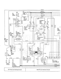
950 Red | F3 Fusible Link (Org) + G1 = Battery 110 Bik Bik Wi we Engine Ground rs Le e ey rh Switch <9 cs ‘Start Chassis Ground G Z Acc Iqn St K1 Neutral Start Relay 115 Bik 115 Bik 105 BIk W4 Frame Ground at Voltage Regulator/Rectifier SE1-Power and Starting Circuits Yel/ Red 300 Red Fi 950 Red 25-Amp 400 Yel/Bik Harness Splice Fuss 500 Yel 332 Org/Wht 790 Blu 410 Pur 400 Pur o X5 S3 (Note " Rear X3 X4 PTO wi Va 750 405 200 S2 of Gn Pur off f Pnk Blu/ x Front X7 Bik PTO X3 X4 = In Gear S6 Switch fi o_¢ V= Neutral oe Seat as! Switch 290 770 fs x9 S5 771 Transmission | Pur/ Neutral Wht Sw CTT 811 Pur gto Pur a | aT 120 Blu , 130 Blu 135 Bik X12 Y1 X10 X13 Front PTO x11 Clutch Al Bik 180 — Bik Time Delay Control Module Harness Splice 135 Bik SE2-PTO and Interlock Circuits 300 Red ‘To SE7-Light Circuit 415 Yel/Blk : Harness Splice t(Light Switch) 1 ane 515 520 PS F Yel Yel 530 950 Engine Grn Red Coolant 525 Temperature 2 — Pnk Lamp ee. P8 N1 Pressure Glow Voltage Lamp Plug Regulator/ s &) |® 620 333 Tan X16 Org/ Wht 315 le} . X20 B6 300 Red A2 a Engine Oil 510 Yel Glow X15 Pressure P Plug vy, Switch Controller XS g00| | 910 BS Yel/ Yel/ Engine 310 ht wht Coolant Red/ 780 |850 Temperature Wht Blu |Pnk X17 Switch 505 140 Yel Bik G2 Alternator 820 Org X19 M2 = P3 Bats Rt ump 438 Battery P7 ad Glow Plugs ‘ X14 ea Discharge Hour = 10 Lamp Meter = ymeDelay 0 a fontrol Module 120 Bik To SE7-Light Circuit Bik = (Head Light Ground)! W25CKisc cee Pkt ef Meee Tr Harness Splice ; | == (Note 2) 135 Blk - SE3-Charging Circuit SE4-Engine Instrumentation Circuits SE5-Fuel System and Glow Plug Circuits 322,330,332 & 430 Lawn & Garden Tractors