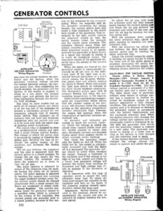
GENERATOR CONTROLS VOLTAGE REGULATOR CUT-OUT AUTO-LITE VOLTAGE REGULATOR Wiring Diagram Generator and close the circuit between the gen- erator and the battery, when the generator terminal voltage exczeds the battery terminal voltage, the con- taet points close, thus completing the circuit between the generator and the battery. If the engine is stopped or idling at a low speed, the contact points open and prevent the battery from discharging through the genera- tor field windings. The relay on some models has an extra set of contact points, one which is on the top side of the armature to provide a convenient ground for the automatic solenoid type of starting motor switch. This auxiliary set of contacts does not have any electrical connection with the control unit and is to be used only with the above type of starting motor installation. The cutout relay is designed to close at a predetermined voltage and open with a small reverse current flowing. The voltage at which the points close is governed by raising or lowering the spring post. Bending the stop up in- creases the spring tension on the armature and increases the closing voltage. The air gap between the armature and the core is measured with the contact points in a closed position, To change the air gap, loosen the two screws holding the armature and move the armature up or down to vary the air gap. The point opening is adjusted by means of the armature stop. On mod- els having the extra set of contact points, the point opening is adjusted by bending the support arm carrying the upper auxiliary contact point. Re- lay contact points should be cleaned occasionally with a small contact file. Never use sandpaper or emery cloth. Current Regulator, The current reg- ulator limits the generator output to a specified value which is governed by the setting of the regulator. The contact points are normally held in a closed position, because of the ten- 354 sion on the armature by the armature spring. When the magnetic pull on the armature overcomes the spring tension, the contact points open: and insert a high resistance in the shunt field circuit of the generator. This re- sistance in the field circuit reduces the generator output so that the spring tension closes the contacts and the output again increases. The armature vibrates many times per second, resulting in a practically con- stant generator output at all speeds, provided the generator is being driven at a speed fast enough to enable it to reach its maximum output, The max’mum output of the generator de- pends upon the setting of the current regulator. When the lights are turned on, the generator output is automatically in- creased by 50 per cent of the addi- tonal load. If the light load is in- creased beyond limitations or a shovt circuit occurs, the bi-metal thermo- stat points open and vibrate, causing the lights to flicker. When this occurs, the light load should be reduced or the short circuit condition eliminated. The thermostat points open with -20 amperes flowing and when the sur- rounding temperature is 210 degrees. Some current regulators are compen- sated for température which means that the current output of the gen- erator will decrease below the normal setting as the operating temperature becomes abnormally high. Likewise, the output will increase when the temperature of operation becomes ab- normally low. An ammeter and voltmeter are needed to check the current regula- tor. Check the voltage at which the cutout relay contact points close and the reverse current at which they open. Gradually increase and decrease engine speed when making checks to obtain accurate meter readings. Now check the generator output with the lights on and off. When the lights are on, the output is automat- ically increased and with the lights off, it is decreased. The generator volt- age should be noted when checking the output. Connect a voltmeter to the regulator and if the voltage is too high or too low, remove and check on a bench. Low generator voltage will prevent the output from reaching its maximum and high voltage may re- sult in damage to the generator or regulator. It is important with this type of regulator, never to exceed the total allowable Jamp load. To check the lamp load connect the ammeter to the reguiator and turn on the lights. If the ammeter reading exceeds speci- fications, reduce the lamp load. Adjustments. Spring tension, meas- ured at the contacts, should be ap- proximately 234 ounces and may be adjusted by slightly bending the con- tact spring. To adjust the air gap, hold down the armature until the fibre bumper barely touches the contact spring post and check the air gap between the armature and center of the core. Ad- just the air gap by bending the con- tact spring post. With the armature down against the lower armature stop, adjust the point opening by bending the lowe- armature stop. With the armature up, adjust the gap between the fibre bumper and contact spring post by bending the upper armature stop. Adjust the current output by slight- ly bending the spring hanger to which the lower end of the spiral spring is attached. Increasing the spring ten- sion increases the current output. De- creasing tension decreases the output.. DELCO-REMY STEP VOLTAGE CONTROL Chrysler Airflow 8, DeSoto, Dodge. Plymouth—1934. Chrysler Imperial 8. Studebaker Commander, President 8, Olfds- mobile 6, 8—1935. Buick 60, 80, 90. Studebaker President 8-—1936. The ste3 voltage control is composed of a volt- age control unit and a cutout relay. The third brush type of generator without some means of voltage con- trol has a tendency to further in- crease its maximum output as the battery approaches a fully charged condition. The purpose of the voltage control unit is to increase or decrease the generator output in accordance with the battery requirements and the connected electrical load. When the battery becomes fully charged, the voltage control unit operates and au- tomatically inserts a resistance in se- ries with the generator field circuit and the generator output is reduced to a safe value. The generator con- tinues to charge at a lower rate as long as the battery is fully charged and the electrical load is small. If the battery becomes partially dis – charged the voltage control vnit ceases to operate and allows the gen- Ciecuir BREAKER AUTO-LITE VOLTAGE and CURRENT REGULATOR Wiring Diagram