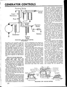
GENERATOR CONTROLS Armature Spring & — f~<—~ Contact , = SS Points Field sey is sg Resistance = a & Fuse TT ; 3 ¢ OE a Voltage Cc = a; elay Contact = = a Points oe a oO = =f SAI = = =a Bat. Generator = Battery 7 Cutout Relay DELCO-REMY, STEP VOLTAGE CONTROL Wiring Diagram the speed of the generator until the output remains constant. Under this condition, the output of the generator will be the amount for which the current regulator is adjusted. It is not absolutely necessary to turn on the lights when checking the current regulator but in case the battery is fully charged, it will prevent exces- sively high voltage within the electri- cal system while making the check. The unit is adjusted as described for the current regulator on 1935 Cadillac cars. AUTO-LITE VOLTAGE REGULATOR Chrysler, DeSoto, Dodge, Packard 120, Plymouth—-1935, 1936. This third - brush type of generator is fitted with a cutout relay and a voltage regula- tor mounted on top of the generator. Two adjustments are provided for the generator, that for changing the rate of charge and for setting the generator cutout relay. Before attempting to set the charge rate connect a jumper wire from the fuse cup to the ground. This cuts out the voltage control unit, which is nec- essary while adjusting the charge rate. Be sure to remove the wire after the charge rate is set. When adjusting the generator charge rate the generator should be removed from the engine and the commutator band removed so that the exact space between the third brush and the main brush can be observed. The third brush rocker ring can then be rotated and should be adjusted so that there 358 are four commutator bars exposed be- tween the third brush and the main brush nearest the third brush. In no case should the brushes be set closer together than this. The cutout relay points close at 6.5 to 7.3 volts and open at 0 to 3 amperes discharge current. Align the points and set the point opening between 015” and .025” by bending the arma- ture stop. Adjust the spring post to obtain the correct voltage for closing the contact points. Bending the post to increase tension will increase the voltage at which the points close. Normally the voltage control relay points are closed and they remain closed when the generator starts to charge the battery. When the battery becomes fully charged and the gener- ator terminal voltage reaches a pre- determined high value, the contact Armature Upper Armature Stop Lower Armature Stop Contact Points Armature Contact Spring Voltage Control Relay DELCO-REMY STEP VOLTAGE CONTROL points open, thereby automatically connecting a resistance into the field circuit of the generator which de- creases the generator charging rate. When the voltage has decreased to its predetermined low value, the contact points will close, shorting out the re- sistance in the field circuit, causing the generator to again charge at the higher rate. This unit prevents the generator voltage from becoming ab- normally high after the battery has reached its fully charged condition, provided the generator third brush is properly set and all connections are clean and tight. This voltage regulator also regulates the charging rate according to tem- perature. It permits the generator to charge at higher rates when the tem- peratures are low and a lower rate when the temperatures are high. The compensation for temperature is ac- complished by the use of a magnetic shunt which by-passes part of the magnetic flow when cold and to a lesser degree when hot. In other words, the resistance in the field cir- cuit which weakens the generator charging rate, is included in the cir- cuit for longer periods during warm weather and shorter periods during cold weather. The voltage regulator also compen- sates the charging rate for increases in load. If the generator is operating on a low rate and a load slightly greater than the low rate is placed on the circuits, the regulator will imme- diately go to the higher rate because of the drop in voltage occasioned by the increase in electrical load. To make adjustments, remove the generator and check it on a test bench. With the armature in the ex- treme downward position, the contact point opening should be set at .008” to 013”. Adjustment is made by bend- ing the upper contact support legs. connect an accurate voltmeter be- tween the terminal marked “BAT” and the ground. With the generator at room temperature, the control re- lay points should open at 8.3 volts and close at 7.3 volts. Because this control unit is overcompensated for tempera- ture change, the hot opening and Field Resistance Armature Stop Armature Spring Armature Contact Points i Cutout Relay