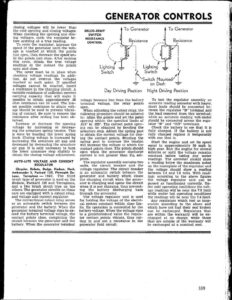
closing voitages will be lower than the cold opening and closing voltages. When checking the opening and clos- ing voltages, cycle the regulator be- fore arriving at a true reading. To cycle the regulator, increase the speed of the generator until the volt- age is reached at which the points just open, then decrease the speed un- til the points just close. After making this cycle, obtain the true voltage readings at the instant the points open and close. ; The cover must be in place when checking voltage readings. In addi- tion, do not overrun the voltages reached at each point. Ii specified voltages cannot be reached, insert a resistance in the charging circuit. A variable resistance of sufficient current carrying capacity that will make it possible to obtain approximately .25 ohm resistance can be used. The low- est possible resistance to attain volt- age should be used to prevent vibrat- ing of contact. Be sure to remove the resistance after setting has been ob- tained. Increase or decrease the opening voltage by increasing or decreas- ing the armature spring tension. This is done by bending the lower spring hook. Closing voltage is increased by increasing the armature air gap and decreased by decreasing the armature air gap. It is only necessary to turn the lower armature stop slightly to obtain the closing voltage adjustment. AUTO-LITE VOLTAGE AND CURRENT REGULATOR Chrysler, DeSota, Dodge, Hudson, Nash, Ambassador 8, Packard 120, Plymouth De- Luxe, Terraplane —- 1937. The third brush type of generator is used on the Hudson, Packard 120 and Terraplane, and a two brush shunt type on the others. The generator circuits on these cars are equipped with a cutout relay, and voltage and current regulator. The conventional cutout relay serves as an automatic switch between the generator and the battery. When the generator terminal voltage rises to ex- ceed the battery terminal voltage, the contact points close, completing the circuit between the generator and the battery. When the generator terminal GENERATOR CONTROLS DELCO-REMY SWITCH RESISTANCE CONTROL sit om fon ny Rien Switch : To Generator Resistance Lighting Switch { Switch Mounted” To Generator Resistance | ! ! ‘ 1 ! j 1 | 4 on Dash = Day Driving Position Night Driving Position voltage becomes less than the battery terminal voltage, the relay points open, When adjusting the cutout relay, the following procedure should be adhered to: Align the points and set the point opening within the specified limits of .015” to .025”. The correct point open- ing can be obtained by bending the armature stop. Adjust the spring post to obtain the correct voltage for clos- ing the contact points. Bending the spring post to increase the tension will increase the voltage at which the contact points close. The points should open when the generator discharge current is not greater than 2% am- peres. The regulator assembly contains two units, the circuit breaker and the voltage regulator. The circuit breaker is an automatic switch between the generator and battery which closes the charging circuit when the gener- | ator is charging and opens the circuit when it is not charging, thus prevent- ing the battery discharging back through the generator. The voltage regulator unit is used for holding the voltage of the electri- cal system constant within close lim- its. Its operation is controlled by the battery voltage. When the voltage rises to a predetermined value the regula-~ tor contact points vibrate, thus cut- ting in and out a resistance in the generator field circuit. To test the regulator assembly an accurate reading ammeter with heavy, short leads should be connected be- tween the regulator “B” terminal and the lead removed from this terminal; while an accurate reading volt-meter should be connected across the regu- lator “B” and “GD” terminals. Check the battery to see that it is fully charged. If the battery is not fully charged replace it temporarily with one that is. Start the engine and set its speed equal to appproximately 30 mph in high gear. Run the engine for several minutes or until the voltage remains constant before taking any meter readings. The ammeter should show a reading below the maximum noted on the nameplate of the regulator and the voltage should show a reading between 7.4 and 7.8 volts. With read~- ings according to the above figures the voltage regulator unit can be passed as functioning correctly. Un- der cold operating conditions the volt- age readings will be near the 7.8 limit while under hot operating conditions the readings will be near the 7.4 limit. Any regulators which test as inop- erative according to the above and which have not had their seal broken ‘can be exchanged. Regulators that are within the warranty will be ex- changed at no charge, while those that are outside of the warranty will be exchanged at a nominal cost. | eee eee