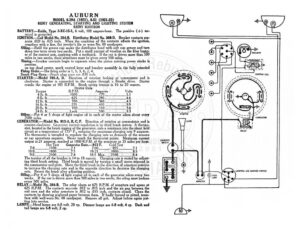
AUBURN MODEL 6-39A (1921), 6-51 (1921-22) REMY GENERATING, STARTING AND LIGHTING SYSTEM REMY IGNITION BATTERY.—Exide, Type 3-XC-15-1, 6 volt, 100 ampere-hour. The positive (+-) ter- minal is grounded. IGNITION.—Coil Model No, 284-B. Distributor Model No. 366-D. Breaker contacts sep- arate .020 to .025 inch. When the condition of the contacts affects the ignition, resurface with a fine, flat jeweler’s file or worn No. 00 sandpaper. Oiling.—Refill the grease cup under the distributor head with soft cup grease and turn down two turns every two weeks. Puta small amount of vaseline on the fiber bump- er of the contact arm, applying with a toothpick. If the car is driven more than 5 miles in two weeks, these attentions must be given every 500 miles. 1 iming.—Breaker contacts begin to separate ah Hi the piston entering power stroke is position. on top dead center, spark control lever and breaker assembly in the fully retarded Firing Order.—The firing order is |, 5, 3, 6, 2, 4. E Plug Gass Shark plug gaps are .030 inch. STARTER:—Model 705-A, D. Direction of rotation looking at commutator end is clockwise. Starter is connected to_the engine through a Bendix drive. Starter cranks the engine at 105 eink ris spring tension is 16 to 20 ounces. tarter Data Torque R.P.M. Amperes Volts Ch | ee, | ||) || eee a a ae eee |i | en «YL Renee any AREY || | Pay ey Aenean. x 12 lb. ft 850 8H 4G 16 Ib. ft 225 ey | ae oe a 20 Ib. ft 100. | RN | ay Se ee IY” 24 Tb feces ees poss OS Ib. ft __Loc ae ee ee sg ak 4 or 5 drops of light engine oil in each of the starter oilers about every miles. GENERATOR :—Model No. 913-A, B,C, F. Direction of rotation at commutator end is counter-clockwise. Generator current regulation is by third brush system. A thermo- stat, located in the brush rigging of the generator, cuts a resistance into the shunt field circuit at a temperature of 175° F., reducing the maximum charging rate 9 amperes. e thermostat is intended to regulate the charging rate as demands of the seasons or car operations requires. Never touch the thermostat points. Maximum current output is 21 i reached at 1800 R.P.M. of the armature or 25 miles per hour. ot Test Generator Data.—913 F. Cold Test 7.01100 7.00. 825 7.1 10.0__. 1800__.._ 7.5 19-21… _-1800, 8.5 DO sie D500 nn J 18.5 Max.__.2500 The tension of all the brushes is 14 to 18 ounces. Charging rate is varied by adjust- ing third brush setting. Third brush is moved by turning a small screw exposed in the commutator end plate. Move the third brush in the direction of armature rotation to increase the charging rate and in the opposite direction to decrease the charging rate. Reseat the brush after adjusting position. Oiling.—Put 4 or 5 drops of light engine oil in each of the generator oilers every two weeks. If the car is driven more than 500 miles in two weeks, the oiling must bedone every 500 miles. RELAY.—Mode! No. 264-B. The relay closes at 675 R.P.M. of armature and opens at 625 R.P.M. _ The contacts separate .012 to .015 inch and the air gap between the coil core and the relay armature is .012 to .015 inch, contacts closed. Clean the contacts by drawing unglazed paper between them. If badly burned or pitted, resur- face with well worn No. 00 sandpaper. Remove all grit. Adjust before again put- ting into service. LAMPS.—Head lamps are 6-8 volt, 20 cp. Dimmer lamps are 6-8 volt, 4 cp. Dash and tail lamps are 6-8 volt, 2 cp. STARTING SwiTCH T Tletelloeg 3 LIGHTING AND IGNITION SWITCH