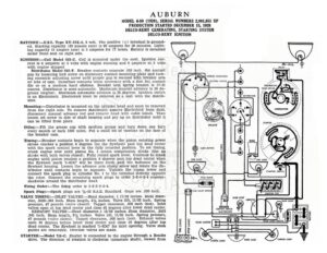
AUBURN MODEL 6-80 (1929), SERIAL NUMBERS 2,981,851 UP PRODUCTION STARTED DECEMBER 15, 1928 DELCO-REMY GENERATING, STARTING SYSTEM DELCO-REMY IGNITION BATTERY:—U.S.L. Type XY-13X-6, 6 volt. The positive (+) terminal is ground- ed. Starting capacity (20 minute rate) is 90 amperes for 20 minutes. Light- ing capacity (5 ampere rate) is 5 amperes for 17 hours. Battery is mounted under front seat on right side. A (ms) wl Q IGNITION :—Coil Model 528-C. Coil is mounted under the cowl. Ignition cur- rent is 4 amperes at 6 volts with engine running and 6 amperes at 6 volts = ST with engine stopped. ‘ 1 RELAY : Distributor Model 641-F. Breaker contacts separate .020 inch. Set contact -@) es Y gap by loosening lock screw on stationary contact mounting plate and turn- o ‘ ss) ing eccentric adjusting screw until proper gap is secured with breaker arm atc, aa tehhio a me on lobe of cam. Resurface contacts when necessary with a fine flat contact LIGHTING SWITCH ae ne 4 file or on a medium hard oilstone. Breaker arm spring tension is 17-21 THERMOSTAT ‘im >, ounces. Distributor is semi-automatic. Maximum manual advance is 20 de- THIRD BRUSH ~ GTA, XN greees (engine). Maximum automatic advance is 22 degrees. Ignition switch i « a is an Electrolock. Electrolock must be removed as a unit with the distrib- oistrigutor | | fh ‘aha: utor. im ) HH Mounting :—Distributor is mounted on the cylinder head and must be removed N y ! from the right side. To remove distributor, remove Electrolock from dash, XN GENERATOR yt disconnect manual advance rod and remove head with cable intact. Then loosen set screw in side of shaft housing and pry up on distributor until it can be lifted from place. Oiling:—Fill the grease cup with medium grease and turn down one turn every month or each 1000 miles. Put a small bit of vaseline on the face of the breaker cam. Timing:—Breaker contacts begin to separate when the piston entering power stroke reaches a position 6 degrees (on the flywheel) past top dead center with the spark control lever in the fully retarded position. To set timing, crank engine over until piston No. 1 enters compression stroke (the up stroke with both valves closed). Fully retard spark lever. Continue to crank engine until piston reaches a position 6 degrees past top dead center when the flywheel mark ‘1-6DC’ will be three teeth past the indicator on the flywheel housing. Loosen the advance arm clamp screw and rotate the dis- tributor until contacts begin to separate. Tighten the clamp screw and connect the spark plug in cylinder No. 1 to the terminal directly opposite the rotor. Connect the remaining spark plugs in order 5-3-6-2-4 counter- clockwise around the distributor head. Firing Order:—The firing order is 1-5-3-6-2-4. Spark Plugs:—Spark plugs are 7%-18 S.A.E. Standard. Gaps are .030 inch. VALVE TIMING:—INLET VALVES:—Head diameter, 1 17/32 inches. Stem diam- eter, .3425-.341 inch. Stem length, 514 inches. Valve lift, 11/32 inch. Spring pressure, 47 pounds (valve closed). Tappet clearance, .006 inch (hot). Inlet valves open at top dead center and close 45 degrees after lower dead center. EXHAUST VALVES:—Head diameter,1 13/32 inches. Stem diameter, .3425 .341 inch. Stem length, 514 inches. Valve lift, 11/32 inch. Spring pressure, 47 pounds (valve closed). Tappet clearance, .008 inch (hot). Exhaust valves open 50 degrees before lower dead center and close 10 degrees after top dead center. The flywheel is marked ‘1-6DC’ for inlet opening. Valve stem guides are removable. Oversize valves are made. STARTER:—Model 716-C. Starter is connected to the engine through a Bendix (1a) (ad) AVA LA RARANVADARAAAANURA RN RDAAR EAA DERE ARMORED CABLE | A Ean vain IGNITION SWITCH ELECTROLOCK STOP LIGHT. drive. The direction of rotation is clockwise (armature shaft), viewed from AUBURN MODEL 6-80 (1929), SERIAL NUMBERS 2,981,851 UP PRODUCTION STARTED DECEMBER 15, 1928 DELCO-REMY GENERATING, STARTING SYSTEM DELCO-REMY IGNITION tne commutator end. Brush spring tension is 24-28 ounces. Starter cranks the engine at 90 R.P.M. drawing 150 amperes at 6 volts. Starter Data Torque R.P.M. Volts Amperes O2lb. Mischa ces SOOO csiccesetescecaeteteoccnn et <1 Gere) ee 70 16 Tnesaweeaeadekane LOCK cS aiemecaceconss Bs d oes secsackal ickdaceencgsevtess 450 Mounting:—Starter is flange mounted at right of engine on forward side of flywheel housing. To remove starter, disconnect cable and remove flange mounting cap screws. Pull starter forward and lift from place. Oiling:—Put 4 or 5 drops of light engine oil in the oiler on the commutator end of the starter every month or each 1000 miles. The drive end bearing is oilless. ; GENERATOR:—Model 955-H. The direction of rotation is counter-clockwise, viewed from the commutator end. Generator current regulation is by third brush shunt field and thermostat. Thermostat contacts open at 175°F. cut- ting the resistance across the thermostat contacts in series with the field and reducing the output approximately 40%. To adjus